Protocols and Standards
- A network is basically all of the components (hardware and software) involved in connecting computers and applications across small and large distances.
- When designing and maintaining a network, remember these factors: cost, security, speed, topology, scalability, reliability, and availability
- some of the more common networking applications include e-mail applications for sending mail electronically, File Transfer Protocol (FTP) applications for transferring files, and web applications for providing a graphical representation of information.
- Protocols are used to implement applications. Some protocols are open standard, meaning that many vendors can create applications that can interoperate with each other, while others are proprietary, meaning that they work only with a particular application
Protocols and standards make networks work together. Protocols make it possible for the various components of a network to communicate with each other, and standards make it possible for different manufacturers’ network components to work together.
A protocol is simply a set of rules that enable effective communications to occur.
Computer networks depend upon many different types of protocols. These protocols are very rigidly defined, and for good reason. Network cards must know how to talk to other network cards to exchange information, operating systems must know how to talk to network cards to send and receive data on the network, and application programs must know how to talk to operating systems to know how to retrieve a file from a network server.
A networking model describes how information is transferred from one networking component to another. Just like a house blueprint defines the materials and technologies that are used in constructing the house, a networking model defines the protocols and devices that are required in building the network.
Technically, a networking model is a comprehensive set of documents that describes how everything should happen in network. Individually, each document describes a functionality, protocol or device that is required by a small portion of the network.
The OSI model is not a networking standard in the same sense that Ethernet and TCP/IP are networking standards. Rather, the OSI model is a framework into which the various networking standards can fit. The OSI model specifies what aspects of a network’s operation can be addressed by various network standards. So, in a sense, the OSI model is sort of a standard of standards.
OSI is a model. It’s called the Open Systems Interconnection Model or OSI model for short. It’s a conceptual model – a means to understand how communications occur. It doesn’t define any protocols or even reference them.
The purpose of the OSI reference model is to guide vendors and developers so the digital communication products and software programs they create can inter operate and to facilitate a clear framework that describes the functions of a networking or telecommunication system.
IT professionals use OSI to model or trace how data is sent or received over a network .
OSI model was created for following purposes:-
- To standardize data networking protocols to allow communication between all networking devices across the entire planet.
- To create a common platform for software developers and hardware manufactures that encourage the creation of networking products that can communicate with each other over the network.
- To help network administrators by dividing large data exchange process in smaller segments. Smaller segments are easier to understand, manage and troubleshoot.
- It is a reference model for how applications communicate over a network.
So models are just a way of understanding something and representing it so that it is more easily understood. Protocols dictate how something actually happens so that two different devices can exchange information if they use the same protocol.
Difference Between OSI Model and TCP/IP Model?
- OSI is a conceptual model which is not practically used for communication, whereas, TCP/IP is used for establishing a connection and communicating through the network.
- TCP/IP stands for Transmission Control Protocol/Internet Protocol. It is a communication protocol used to interconnect network devices on the internet.
TCP/IP protocol specifies how data is exchanged over the internet by providing end-to-end communications that identify how it should be broken into packets, addressed, transmitted, routed and received at the destination.
OSI Model and TCP/IP Comparison Table
Let us discuss the topmost differences between OSI Model vs TCP/IP Model.
| OSI Model | TCP/IP Model |
| It stands for Open Systems Interconnection | It stands for Transmission Control and Internet Protocol. |
| It is a theoretical framework for the computer environment. | It is a customer service model that is used for data information transmission. |
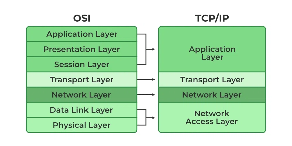
| In the OSI model, there are 7 Layers | 4 Layers are present in the TCP/IP model |
| Low in use | TCP/IP model is mostly used |
| This model is an approach in Vertical | This model is an approach in horizontal |
| In this model delivery of package is a guarantee | In this model delivery of package is not assured |
| The protocol is hidden in OSI and can be easily substituted and changes in technology. | In this model replacing tool is not easy as like OSI |

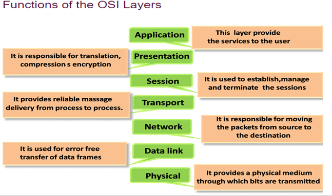
The Seven Layers of the OSI Model :

1)
| Physical | Governs the layout of cables and devices, such as repeaters and hubs. |
- The Physical Layer mainly defines standards for media and devices that are used to move the data across the network. 10BaseT, 10Base100, CSU/DSU, DCE and DTE are the few examples of the standards used in this layer.
- The bottom layer of the OSI model is the Physical layer. It addresses the physical characteristics of the network, such as the types of cables used to connect devices, the types of connectors used, how long the cables can be, and so on
- For example, the Ethernet standard for 10BaseT cable specifies the electrical characteristics of the twisted-pair cables, the size and shape of the connectors, the maximum length of the cables, and so on
- Another aspect of the Physical layer is the electrical characteristics of the signals used to transmit data over the cables from one network node to another. The Physical layer doesn’t define any meaning to those signals other than the basic binary values of 1 and 0. The higher levels of the OSI model must assign meanings to the bits that are transmitted at the Physical layer.
- One type of Physical layer device commonly used in networks is a repeater, which is used to regenerate the signal whenever you need to exceed the cable length allowed by the Physical layer standard.
- The network adapter (also called a network interface card; NIC) installed in each computer on the network is a Physical layer device.
- Encoding of digital signals received from the Data Link layer based on the attached media type such as electrical for copper, light for fiber, or a radio wave for wireless.
- On sending computer, it converts digital signals received from the Data Link layer, in analog signals and loads them in physical media.
- On receiving computer, it picks analog signals from media and converts them in digital signals and transfers them to the Data Link layer for further processing
Functions of a Physical layer:
- Line Configuration: It defines the way how two or more devices can be connected physically.
- Data Transmission: It defines the transmission mode whether it is simplex, half-duplex or full-duplex mode between the two devices on the network.
- Topology: It defines the way how network devices are arranged.
- Signals: It determines the type of the signal used for transmitting the information.
- Bit rate control: The Physical layer also defines the transmission rate i.e. the number of bits sent per second.
Data Link Layer :
The data link layer is responsible for the node to node delivery of the message. The main function of this layer is to make sure data transfer is error free from one node to another, over the physical layer. When a packet arrives in a network, it is the responsibility of DLL to transmit it to the Host using its MAC address.
The data link layer effectively separates the media transitions that occur as the packet is forwarded from the communication processes of the higher layers. The data link layer receives packets from and directs packets to an upper layer protocol, in this case IPv4 or IPv6. This upper layer protocol does not need to be aware of which media the communication will use.
Data Link Layer is divided into two sub layers :
- Logical Link Control (LLC)
- Media Access Control (MAC)
- Since the physical layer merely accepts and transmits a stream of bits without any regard to the meaning of the structure, it is up to the data link layer to create and recognize frame boundaries. This can be accomplished by attaching special bit patterns to the beginning and end of the frame. Encryption can be used to protect the message as it flows between each network node. Each node then decrypts the message received and re-encrypts it for transmission to the next node.
- The protocol packages the data into frames that contain source and destination addresses
- These frames refer to the physical hardware address of each network card attached to the network cable.
- Ethernet, Token Ring, and ARCnet are examples of LAN data link protocols
- The data link layer sends blocks of data with the necessary synchronization, bit error detection/correction error control, and flow control.
- Since the physical layer merely accepts and transmits a stream of bits without any regard to the meaning of the structure, it is up to the data link layer to create and recognize frame boundaries
- DLL also encapsulates Sender and Receiver’s MAC address in the header
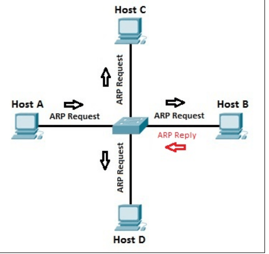
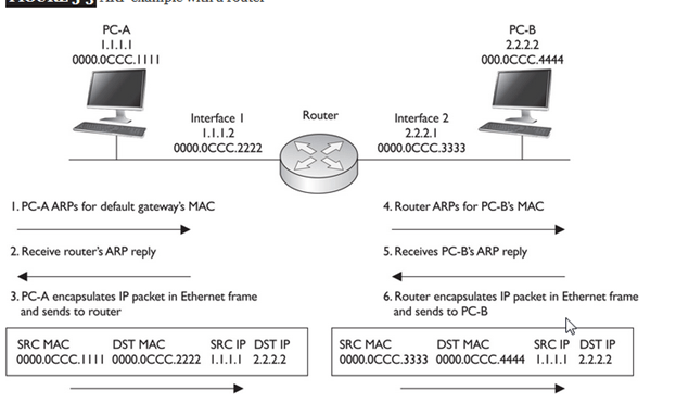
The Receiver’s MAC address is obtained by placing an ARP(Address Resolution Protocol) request onto the wire asking “Who has that IP address?” and the destination host will reply with its MAC address.
- Framing: Framing is a function of the data link layer. It provides a way for a sender to transmit a set of bits that are meaningful to the receiver. This can be accomplished by attaching special bit patterns to the beginning and end of the frame.
Physical addressing: After creating frames, Data link layer adds physical addresses (MAC address) of sender and/or receiver in the header of each frame.
- Error control: Data link layer provides the mechanism of error control in which it detects and retransmits damaged or lost frames.
- Flow Control: The data rate must be constant on both sides else the data may get corrupted thus , flow control coordinates that amount of data that can be sent before receiving acknowledgement.
- Access control: When a single communication channel is shared by multiple devices, MAC sub-layer of data link layer helps to determine which device has control over the channel at a given time.
Switch & Bridge are Data Link Layer devices
- Bridge: An intelligent repeater that’s aware of the MAC addresses of the nodes on either side of the bridge and can forward packets accordingly.
- Switch: An intelligent hub that examines the MAC address of arriving packets to determine which port to forward the packet to.

- The data link layer functionality is usually split it into logical sub-layers, the upper sub-layer, termed as LLC, that interacts with the network layer above and the lower sub-layer, termed as MAC, that interacts with the physical layer below,
The primary responsibilities of LLC are:
Network Layer protocol Multiplexing/De-Multiplexing
Interfacing with the Network (Layer3) above by doing L3 protocol multiplexing/de-multiplexing. On receiving a frame from the physical layer below, the LLC is responsible for looking at the L3 Protocol type and handing over the datagram to the correct L3 protocol (de-multiplexing) at the network layer above. On the sending side, LLC takes packets from different L3 protocols like IP, IPX, ARP etc., and hands it over to the MAC layer after filling the L3 protocol type in the LLC header portion of the frame (multiplexing)
Logical Link Services
LLC can optionally provide reliable frame transmission by the sending node numbering each transmitted frame (sequence number), the receiving node acknowledging each received frame ( acknowledgment number) and the sending node retransmitting lost frames. It can also optionally provide flow control by allowing the receivers to control the sender’s rate through control frames like RECEIVE READY and RECEIVE NOT READY etc.
MAC
Layer 2 protocols specify the encapsulation of a packet into a frame and the techniques for getting the encapsulated packet on and off each medium. The technique used for getting the frame on and off media is called the media access control method.]
It provides data link layer addressing and delimiting of data according to the physical signaling requirements of the medium and the type of data link layer protocol in use
As packets travel from source host to destination host, they typically traverse over different physical networks. These physical networks can consist of different types of physical media such as copper wires, optical fibers, and wireless consisting of electromagnetic signals, radio and microwave frequencies, and satellite links.
The packets do not have a way to directly access these different media. It is the role of the OSI data link layer to prepare network layer packets for transmission and to control access to the physical media. The media access control methods described by the data link layer protocols define the processes by which network devices can access the network media and transmit frames in diverse network environments.
Without the data link layer, network layer protocols such as IP, would have to make provisions for connecting to every type of media that could exist along a delivery path. Moreover, IP would have to adapt every time a new network technology or medium was developed. This process would hamper protocol and network media innovation and development. This is a key reason for using a layered approach to networking.
The MAC sub-layer interacts with the physical layer and is primarily responsible for framing/de-framing and collision resolution.
Framing/De-Framing and interaction with PHY: On the sending side, the MAC sub-layer is responsible for creation of frames from network layer packets, by adding the frame header and the frame trailer. While the frame header consists of layer2 addresses (known as MAC address) and a few other fields for control purposes, the frame trailer consists of the CRC/checksum of the whole frame. After creating a frame, the MAC layer is responsible for interacting with the physical layer processor (PHY) to transmit the frame.
On the receiving side, the MAC sub-layer receives frames from the PHY and is responsible for accepting each frame, by examining the frame header. It is also responsible for verifying the checksum to conclude whether the frame has come uncorrupted through the link without bit errors.
Collision Resolution : On shared or broadcast links, where multiple end nodes are connected to the same link, there has to be a collision resolution protocol running on each node, so that the link is used cooperatively. The MAC sub-layer is responsible for this task and it is the MAC sub-block that implements standard collision resolution protocols like CSMA/CD, CSMA etc. For half-duplex links, it is the MAC sub-layer that makes sure that a node sends data on the link only during its turn. For full-duplex point-to-point links, the collision resolution functionality of MAC sub-layer is not required.
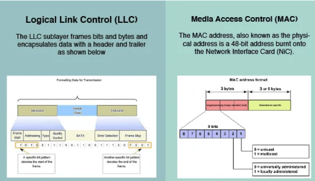

The figure illustrates how the data link layer is separated into the LLC and MAC sublayers. The LLC communicates with the network layer while the MAC sublayer allows various network access technologies. For instance, the MAC sublayer communicates with Ethernet LAN technology to send and receive frames over copper or fiber-optic cable. The MAC sublayer also communicates with wireless technologies such as Wi-Fi and Bluetooth to send and receive frames wirelessly
Layer 2 Frame Structure:
Formatting Data for Transmission
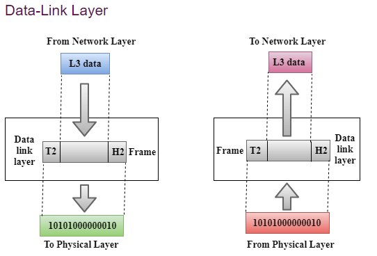
The data link layer prepares a packet for transport across the local media by encapsulating it with a header and a trailer to create a frame. The description of a frame is a key element of each data link layer protocol.
The data link layer frame includes:
Header: Contains control information, such as addressing, and is located at the beginning of the PDU.
Data: Contains the IP header, transport layer header, and application data.
Trailer: Contains control information for error detection added to the end of the PDU
Creating a Frame
When data travels on the media, it is converted into a stream of bits, or 1s and 0s. If a node is receiving long streams of bits, how does it determine where a frame starts and stops or which bits represent the address?
Framing breaks the stream into decipherable groupings, with control information inserted in the header and trailer as values in different fields. This format gives the physical signals a structure that can be received by nodes and decoded into packets at the destination.
Generic Frame Fields:

Frame start and stop indicator flags
Used by the MAC sublayer to identify the beginning and end limits of the frame
Addressing
Used by the MAC sublayer to identify the source and destination nodes.
Type
Used by the LLC to identify the Layer 3 protocol
Control
Identifies special flow control services.
Data
Contains the frame payload (i.e., packet header, segment header, and the data.
Error Detection
Included after the data to form the trailer, these frame fields are used for error detection
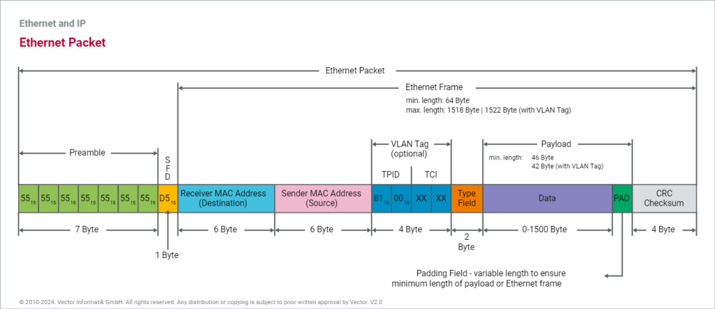
The Frame
Although there are many different data link layer protocols that describe data link layer frames, each frame type has three basic parts:Header ,Data ,Trailer
All data link layer protocols encapsulate the Layer 3 PDU within the data field of the frame. However, the structure of the frame and the fields contained in the header and trailer vary according to the protocol.
The data link layer protocol describes the features required for the transport of packets across different media. These features of the protocol are integrated into the encapsulation of the frame. When the frame arrives at its destination and the data link protocol takes the frame off the media, the framing information is read and discarded.
There is no one frame structure that meets the needs of all data transportation across all types of media. Depending on the environment, the amount of control information needed in the frame varies to match the media access control requirements of the media and logical topology.
A fragile environment requires more control. However, a protected environment requires fewer controls.
The Header
The frame header contains the control information specified by the data link layer protocol for the specific logical topology and media used.
Frame control information is unique to each type of protocol. It is used by the Layer 2 protocol to provide features demanded by the communication environment.
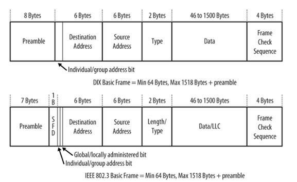
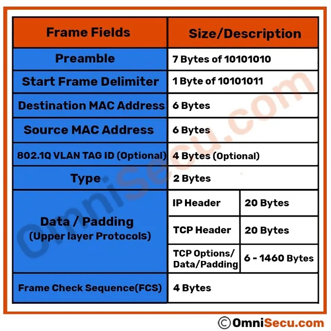
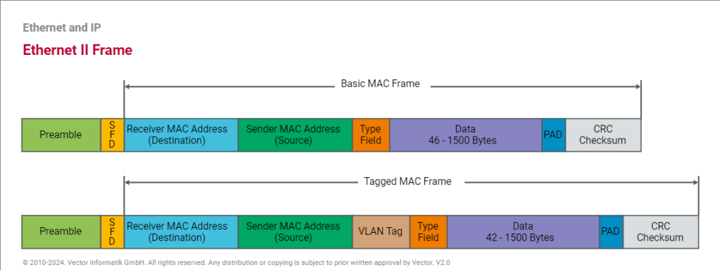
The Ethernet frame header fields are as follows:
Start Frame field: Indicates the beginning of the frame.
Source and Destination Address fields: Indicates the source and destination nodes on the media.
Type field: Indicates the upper layer service contained in the frame.
Different data link layer protocols may use different fields from those mentioned. For example other Layer 2 protocol header frame fields could include:
Priority/Quality of Service field: Indicates a particular type of communication service for processing.
Logical connection control field: Used to establish a logical connection between nodes.
Physical link control field: Used to establish the media link.Flow control field: Used to start and stop traffic over the media.Congestion control field: Indicates congestion in the media.
Because the purposes and functions of data link layer protocols are related to the specific topologies and media, each protocol has to be examined to gain a detailed understanding of its frame structure. As protocols are discussed in this course, more information about the frame structure will be explained.
Layer 2 Address
The data link layer provides addressing that is used in transporting a frame across a shared local media. Device addresses at this layer are referred to as physical addresses. Data link layer addressing is contained within the frame header and specifies the frame destination node on the local network. The frame header may also contain the source address of the frame.
Unlike Layer 3 logical addresses, which are hierarchical, physical addresses do not indicate on what network the device is located. Rather, the physical address is a unique device specific address. If the device is moved to another network or subnet, it will still function with the same Layer 2 physical address.
An address that is device-specific and non-hierarchical cannot be used to locate a device across large networks or the Internet. This would be like trying to find a single house within the entire world, with nothing more than a house number and street name. The physical address, however, can be used to locate a device within a limited area. For this reason, the data link layer address is only used for local delivery. Addresses at this layer have no meaning beyond the local network. Compare this to Layer 3, where addresses in the packet header are carried from source host to destination host regardless of the number of network hops along the route.
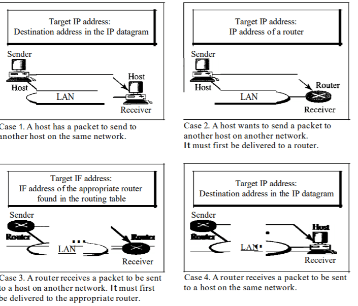
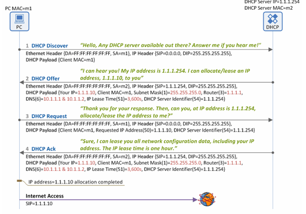
If the data must pass onto another network segment, an intermediate device, such as a router, is necessary. The router must accept the frame based on the physical address and de-encapsulate the frame in order to examine the hierarchical address, or IP address. Using the IP address, the router is able to determine the network location of the destination device and the best path to reach it. Once it knows where to forward the packet, the router then creates a new frame for the packet, and the new frame is sent onto the next segment toward its final destination.
The Trailer
Data link layer protocols add a trailer to the end of each frame. The trailer is used to determine if the frame arrived without error. This process is called error detection and is accomplished by placing a logical or mathematical summary of the bits that comprise the frame in the trailer. Error detection is added at the data link layer because the signals on the media could be subject to interference, distortion, or loss that would substantially change the bit values that those signals represent.
A transmitting node creates a logical summary of the contents of the frame. This is known as the cyclic redundancy check (CRC) value. This value is placed in the Frame Check Sequence (FCS) field of the frame to represent the contents of the frame..
When the frame arrives at the destination node, the receiving node calculates its own logical summary, or CRC, of the frame. The receiving node compares the two CRC values. If the two values are the same, the frame is considered to have arrived as transmitted. If the CRC value in the FCS differs from the CRC calculated at the receiving node, the frame is discarded.
Therefore, the FCS field is used to determine if errors occurred in the transmission and reception of the frame. The error detection mechanism provided by the use of the FCS field discovers most errors caused on the media.
There is always the small possibility that a frame with a good CRC result is actually corrupt. Errors in bits may cancel each other out when the CRC is calculated. Upper layer protocols would then be required to detect and correct this data loss.
THE NETWORK LAYER :
The Network layer handles the task of routing network messages from one computer to another. The two most popular Layer 3 protocols are IP (which is usually paired with TCP) and IPX (typically paired with SPX for use with Novell and Windows networks).
Network layer protocols provide two important functions: logical addressing and routing. The following sections describe these functions.
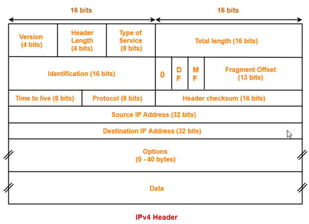
The third layer of OSI model is the Network Layer. This layer takes data segment from transport layer and adds logical address to it. A logical address has two components; network partition and host partition. Network partition is used to group networking components together while host partition is used to uniquely identity a system on a network. Logical address is known as IP address. Once logical address and other related information are added in segment, it becomes packet.
To move data packet between two different networks, a device known as router is used. Router uses logical address to take routing decision. Routing is a process of forwarding data packet to its destination.
- Defining logical addresses and finding the best path to reach the destination are the main functions of this layer. Router works in this layer.
Functions of Network Layer:
- Internetworking: An internetworking is the main responsibility of the network layer. It provides a logical connection between different devices.
- Addressing: A Network layer adds the source and destination address to the header of the frame. Addressing is used to identify the device on the internet.
- Routing: Routing is the major component of the network layer, and it determines the best optimal path out of the multiple paths from source to the destination.
- Packetizing: A Network Layer receives the packets from the upper layer and converts them into packets. This process is known as Packetizing. It is achieved by internet protocol (IP).
THE TRANSPORT LAYER
- The Transport layer is where you find two of the most well-known networking protocols: TCP (typically paired with IP) and SPX (typically paired with IPX).
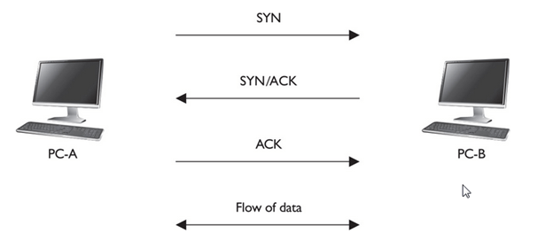
- The main purpose of the Transport layer is to ensure that packets are transported reliably and without errors. The Transport layer does this task by establishing connections between network devices, acknowledging the receipt of packets, and resending packets that aren’t received or are corrupted when they arrive .
- Main functionalities of transport layer are segmentation, data transportation and connection multiplexing. For data transportation, it uses TCP and UDP protocols. TCP is a connection-oriented protocol. It provides reliable data delivery.
- The two protocols used in this layer are:
- Transmission Control Protocol
- It is a standard protocol that allows the systems to communicate over the internet.
- It establishes and maintains a connection between hosts.
- When data is sent over the TCP connection, then the TCP protocol divides the data into smaller units known as segments. Each segment travels over the internet using multiple routes, and they arrive in different orders at the destination. The transmission control protocol reorders the packets in the correct order at the receiving end.
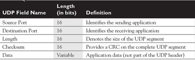
- User Datagram Protocol
- User Datagram Protocol is a transport layer protocol.
- It is an unreliable transport protocol as in this case receiver does not send any acknowledgment when the packet is received, the sender does not wait for any acknowledgment. Therefore, this makes a protocol unreliable.
- Common protocols: Transmission Control Protocol (TCP), User Datagram Protocol (UDP), Sequenced Packet Exchange (SPX), Name-Binding Protocol (NBP)
THE SESSION LAYER
- The Session layer establishes conversations — sessions — between networked devices. A session is an exchange of connection-oriented transmissions between two network devices. Each transmission is handled by the Transport layer protocol. The session itself is managed by the Session layer protocol.
- A single session can include many exchanges of data between the two computers involved in the session. After a session between two computers has been established, it’s maintained until the computers agree to terminate the session.
The Session layer allows three types of transmission modes:
• Simplex: Data flows in only one direction.
• Half-duplex: Data flows in both directions, but only in one direction at a time.
• Full-duplex: Data flows in both directions at the same time.
- It is responsible for setting up, managing, and dismantling sessions between presentation layer entities and providing dialogs between computers.
When an application makes a network request, this layer checks whether the requested resource is available in local system or in remote system. If requested resource is available in remote system, it tests whether a network connection to access that resource is available or not. If network connection is not available, it sends an error message back to the application informing that connection is not available .
The session layer is responsible establishing, managing, and terminating communications between two computers. RPCs and NFS are the examples of the session layer.
Functions of Session layer:
- Dialog control: Session layer acts as a dialog controller that creates a dialog between two processes or we can say that it allows the communication between two processes which can be either half-duplex or full-duplex.
- Synchronization: Session layer adds some checkpoints when transmitting the data in a sequence. If some error occurs in the middle of the transmission of data, then the transmission will take place again from the checkpoint. This process is known as Synchronization and recovery.

Presentation Layer :
- The presentation layer works as the translator in OSI model.
- When receiving data from application layer, it converts that data in such a format that can be sent over the network. When receiving data from session layer, it reconverts that data in such a format that the application which will use the incoming data can understand.
- The Presentation layer is responsible for how data is represented to applications.
- Besides simply converting data from one code to another, the Presentation layer can also apply sophisticated compression techniques so that fewer bytes of data are required to represent the information when it’s sent over the network. At the other end of the transmission, the Presentation layer then uncompresses the data .
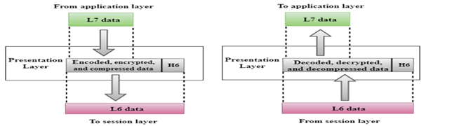
Convert, compress and encrypt are the main functions which presentation layer performs in sending computer while in receiving computer there are reconvert, decompress and decrypt. ASCII, BMP, GIF, JPEG, WAV, AVI, and MPEG are the few examples of standards and protocols which work in this layer.
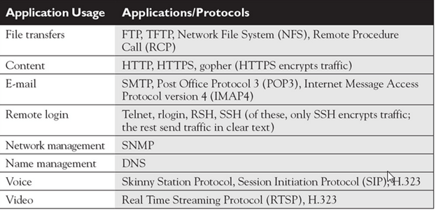
THE APPLICATION LAYER
- The highest layer of the OSI model, the Application layer deals with the techniques that application programs use to communicate with the network.
- An application program is considered as network-aware when it can make any sort of network request. If an application program can’t make any kind of network request, it is considered as network-unaware program.
- The name of this layer is a little confusing. Application programs (such as Microsoft Office or Quick Books) aren’t a part of the Application layer. Rather, the Application layer represents the programming interfaces that application programs use to request network services.
Network-aware programs are further divided in two categories;
- Programs which are mainly created to work in local system but if require can connect with remote system such as MS-Word, Adobe-Photoshop, VLC Player, etc.
- Programs which are mainly created to work with remote system such as SSH, FTP, TFTP, etc
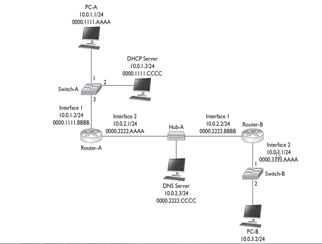
Top layer of OSI model is application layer. It provides the protocols and services that are required by the network-aware applications to connect with the network. FTP, TFTP, POP3, SMTP and HTTP are the few examples of standards and protocols used in this layer.Hypertext Transfer Protocol (HTTP), Hypertext Transfer Protocol Secure (HTTPS), Telnet, Secure Shell (SSH), File Transfer Protocol (FTP), Trivial File Transfer Protocol (TFTP), Simple Mail Transfer Protocol (SMTP), Post Office Protocol 3 (POP3), Dynamic Host Configuration Protocol (DHCP), Domain Name System (DNS), Network Time Protocol (NTP)
The OSI reference model Working
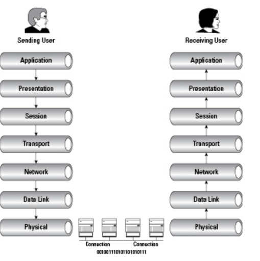
Delivering the data using seven conceptual layers defined by the ISO, these layers divide network communications architecture in a top-to-bottom approach. Moving up the OSI model from the bottommost layer to the top, services are provided to the next-uppermost layer (by the layer just below it), while services are received from the topmost layer to each next-lower layer. Each layer is responsible for a specific, exclusive set of functions not handled at any other layer.
Communication is possible with layers above and below a given layer on the same system and its peer layer on the other side of the connection. The network layer may prepare and hand data off to either the transport or data link layer, depending on the direction of network traffic. If data is being received, it flows up the stack. Data that is being sent travels down the stack. The network layer on the sending computer also communicates with the network layer on the receiving computer, its peer layer.
A good way to remember the names of each layer is to use the mnemonic device “All People Seem To Need Data Processing” (from the top down), or in reverse order, “Please Do Not Throw Sausage Pizza Away.”
What is the layer?
A layer is an independent entity that implements a fixed set of functionalities. A layer provides services to the upper layer and uses the services of the lower layer.
What are primitives?
Services offered by a layer is defined in terms of primitives. E.g a transport layer sends the message on user request, so one of the primitives is the message transfer request

Peer To Peer Communication In OSI Model:
First, we will explain what peer to peer communication is? What is a peer in the OSI model? A peer is a remote layer at the same level. For example. The transport layer of the remote protocol stack is the peer of the local transport layer. When a local peer sends a message to the remote, it adds its address and peer address in the header. For the lower layer, the header is user data only. The remote peer uses the header to handle the message.

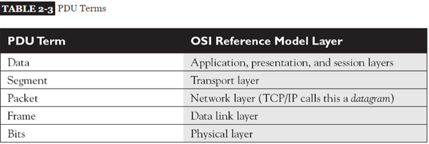
PDU In The OSI Model:
Protocol data unit or PDU in networking is the information unit exchange between the two layers. There is one to one relationship between a primitive and protocol data unit. A PDU contains a header part and the data part. The header part is optional. In the OSI model till layer 4 a PDU has header and data. From layers 4 to 7 there is only user data.
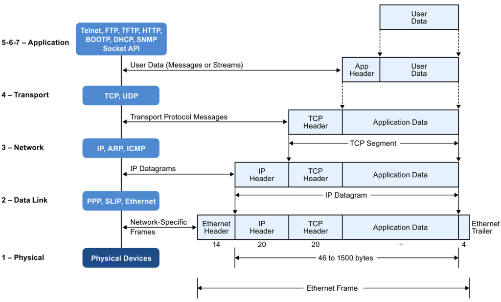
Demystifying data encapsulation
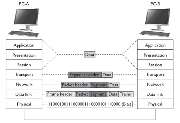
Encapsulation in telecommunications is defined as the inclusion of one data structure inside another so that the first data structure is temporarily hidden from view. Data is encapsulated and decapsulated in this way as it travels through the different layers of the OSI
Starting from the application layer and moving downward, user information is formed into data and handed to the presentation layer for encapsulation. The presentation layer encapsulates the data provided by the application layer and passes it on to the session layer. The session layer synchronizes with the corresponding session layer on the destination host and passes the data to the transport layer, which converts the data into segments and delivers these segments from source to destination. The network layer encapsulates the segments from the transport layer into packets, or datagrams, and gives a network header defining the source and destination IP addresses. These packets of data are given to the data link layer and converted into frames. Frames are then converted into binary data, ready for network transfer.

1. User information is processed by the application, presentation, and session layers and prepares the data for transmission.
For example, Robert opens his Web browser application on his laptop and types in the URL http://www.cisco.com.
2. The upper layers present the data to the transport layer, which converts the user data into segments.
Continuing with the example, Robert’s data request passes down from the upper layers to the transport layer and a header is added, acknowledging the HTTP request.
3. The network layer receives the segments and converts them into packets.
The transport layer passes the data down to the network layer, where source and destination information is added, providing the address to the destination.
4. The data link layer converts the packets into frames.
The data link layer frames the packets and adds the Ethernet hardware address of the source computer and the MAC address of the nearest connected device on the remote network.
5. The physical layer receives the data frames and converts them into binary format.
Data frames are converted into bits and transmitted over the network, returning Robert’s requested Web page.