A VLAN is a group of devices in the same broadcast domain or subnet. VLANs are good at logically separating/segmenting traffic between different groups of users. VLANs contain/isolate broadcast traffic, where you need a router to move traffic between VLANs. VLANs create separate broadcast domains: they increase the number of broadcast domains, but decrease the size of the broadcast domains.
- layer 2 devices, including bridges and switches, always propagate certain kinds of traffic in the broadcast domain.
- It affects the bandwidth of these devices’ connections as well as their local processing. If you were using bridges, the only solution available to solve this problem would be to break up the broadcast domain into multiple broadcast domains and interconnect these domains with a router.
- With this approach, each new broadcast domain would be a new logical segment and would need a unique network number to differentiate it from the other layer 3 logical segments.
- Unfortunately, this is a costly solution, since each broadcast domain, each logical segment, needs its own port on a router. The more broadcast domains that you have from bridges, the bigger the router required
VLAN Overview
A virtual LAN (VLAN) is a logical grouping of network devices in the same broadcast domain that can span multiple physical segments.
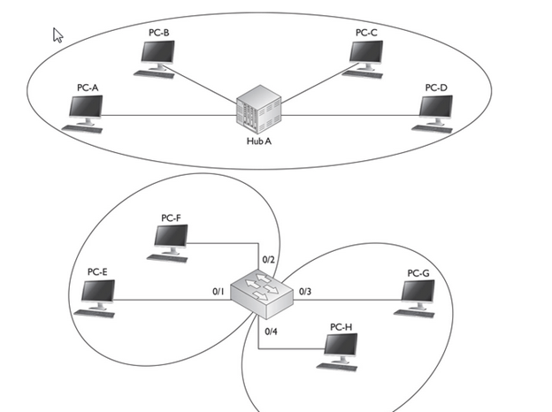
- By default, all ports on a switch are in the same broadcast domain. In this example, however, the configuration of the switch places PC-E and PC-F in one broadcast domain (VLAN) and PC-G and PC-H in another broadcast domain.
- Switches are used to create VLANs, or separate broadcast domains. VLANs are not restricted to any physical boundary in the switched network, assuming that all the devices are interconnected via switches and that there are no intervening layer 3 devices. For example, a VLAN could be spread across multiple switches, or it could be contained in the same switch, as is shown in Figure

- This example shows three VLANs. Notice that VLANs are not tied to any physical location: PC-A, PC-B, PC-E, and PC-F are in the same VLAN but are connected to different ports of different switches. However, a VLAN could be contained to one switch, as PC-C and PC-D are connected to SwitchA.
Subnets and VLANs
Logically speaking, VLANs are also subnets. A subnet, or a network, is a contained broadcast domain. A broadcast that occurs in one subnet will not be forwarded, by default, to another subnet. Routers, or layer 3 devices, provide this boundary function. Each of these subnets requires a unique network number. And to move from one network number to another, you need a router. In the case of broadcast domains and switches, each of these separate broadcast domains is a separate VLAN; therefore, you still need a routing function to move traffic between different VLANs.
Remember that each VLAN must be associated with a unique subnet or network number.
Advantage of VLAN
VLAN provides following advantages:-
- Solve broadcast problem
- Reduce the size of broadcast domains
- Allow us to add additional layer of security
- Make device management easier
- Allow us to implement the logical grouping of devices by function instead of location
Solve broadcast problem
When we connect devices into the switch ports, switch creates separate collision domain for each port and single broadcast domain for all ports. Switch forwards a broadcast frame from all possible ports. In a large network having hundreds of computers, it could create performance issue. Of course we could use routers to solve broadcast problem, but that would be costly solution since each broadcast domain requires its own port on router. Switch has a unique solution to broadcast issue known as VLAN. In practical environment we use VLAN to solve broadcast issue instead of router.
Each VLAN has a separate broadcast domain. Logically VLANs are also subnets. Each VLAN requires a unique network number known as VLAN ID. Devices with same VLAN ID are the members of same broadcast domain and receive all broadcasts. These broadcasts are filtered from all ports on a switch that aren’t members of the same VLAN.
Reduce the size of broadcast domains
VLAN increase the numbers of broadcast domain while reducing their size. For example we have a network of 100 devices. Without any VLAN implementation we have single broadcast domain that contain 100 devices. We create 2 VLANs and assign 50 devices in each VLAN. Now we have two broadcast domains with fifty devices in each. Thus more VLAN means more broadcast domain with less devices
Allow us to add additional layer of security
VLANs enhance the network security. In a typical layer 2 network, all users can see all devices by default. Any user can see network broadcast and responds to it. Users can access any network resources located on that specific network. Users could join a workgroup by just attaching their system in existing switch. This could create real trouble on security platform. Properly configured VLANs gives us total control over each port and users. With VLANs, you can control the users from gaining unwanted access over the resources. We can put the group of users that need high level security into their own VLAN so that users outside from VLAN can’t communicate with them.
Make device management easier
Device management is easier with VLANs. Since VLANs are a logical approach, a device can be located anywhere in the switched network and still belong to the same broadcast domain. We can move a user from one switch to another switch in same network while keeping his original VLAN. For example our company has a five story building and a single layer two network. In this scenario, VLAN allows us to move the users from one floor to another floor while keeping his original VLAN ID. The only limitation we have is that device when moved, must still be connected to the same layer 2 network.
Different VLAN can communicate only via Router where we can configure wild range of security options.
Since this is a logical segmentation and not a physical one, workstations do not have to be physically located together. Users on different floors of the same building, or even in different buildings can now belong to the same LAN.
Scalability
Through segmentation of broadcast domains, VLANs increase your network’s scalability. Since VLANs are a logical construct, a user can be located anywhere in the switched network and still belong to the same broadcast domain. If you move a user from one switch to another switch in the same switched network, you can still keep the user in his or her original VLAN
Many network administrators use VLANs not only to separate different types of user traffic (commonly separated by job function), but also to separate it based on the type of traffic, placing network management, multicast, and voice over IP (VoIP) traffic into their own distinctive VLANs .Different data types, such as delay-sensitive voice or video (multicast), network management, and data application traffic, should be separated into different VLANs via connected switches to prevent problems in one data type from affecting others.
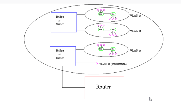
- VLAN’s also allow broadcast domains to be defined without using routers. Bridging software is used instead to define which workstations are to be included in the broadcast domain. Routers would only have to be used to communicate between two VLAN’s
VLAN Membership
VLAN membership can be assigned to a device by one of two methods
- Static
- Dynamic
These methods decide how a switch will associate its ports with VLANs.
Static
Assigning VLANs statically is the most common and secure method. It is pretty easy to set up and supervise. In this method we manually assign VLAN to switch port. VLANs configured in this way are usually known as port-based VLANs.
Static method is the most secure method also. As any switch port that we have assigned a VLAN will keep this association always unless we manually change it. It works really well in a networking environment where any user movement within the network needs to be controlled.
Dynamic
In dynamic method, VLANs are assigned to port automatically depending on the connected device. In this method we have configure one switch from network as a server. Server contains device specific information like MAC address, IP address etc. This information is mapped with VLAN. Switch acting as server is known as VMPS (VLAN Membership Policy Server). Only high end switch can configured as VMPS. Low end switch works as client and retrieve VLAN information from VMPS.
Dynamic VLANs supports plug and play movability. For example if we move a PC from one port to another port, new switch port will automatically be configured to the VLAN which the user belongs. In static method we have to do this process manually.
- Dynamic VLANs have one main advantage over static VLANs: they support plug-and-play movability. For instance, if you move a PC from a port on one switch to a port on another switch and you are using dynamic VLANs, the new switch port will automatically be configured for the VLAN to which the user belongs. About the only time that you have to configure information with dynamic VLANs.
- If you are using static VLANs, not only will you have to configure the switch port manually with this updated information, but, if you move the user from one switch to another, you will also have to perform this manual configuration to reflect the user’s new port.
- One advantage, though, that static VLANs have over dynamic VLANs is that the configuration process is easy and straightforward. Dynamic VLANs require a lot of initial preparation involving matching users to VLANs
VLAN Connections
During the configuration of VLAN on port, we need to know what type of connection it has.
Switch supports two types of VLAN connection
- Access link
- Trunk link
- Access link connections can be associated only with a single VLAN (voice VLAN ports are an exception to this). This means that any device or devices connected to this port will be in the same broadcast domain.
- An access link connection is a connection between a switch and a device with a normal Ethernet NIC, where the Ethernet frames are transmitted unaltered (untagged). An access link connection normally can be associated only with a single VLAN.
- For example, if ten users are connected to a hub, and you plug the hub into an access link interface on a switch, then all of these users will belong to the same VLAN that is associated with the switch port. If you wanted five users on the hub to belong to one VLAN and the other five to a different VLAN, you would need to purchase an additional hub and plug each hub into a different switch port. Then, on the switch, you would need to configure each of these ports with the correct VLAN identifier.

Trunk Connections
- Unlike access link connections, trunk connections are capable of carrying traffic for multiple VLANs. To support trunking, the original Ethernet frame must be modified to carry VLAN information, commonly called a VLAN identifier or number. This ensures that the broadcast integrity is maintained. For instance, if a device from VLAN 1 has generated a broadcast and the connected switch has received it, when this switch forwards it to other switches, these switches need to know the VLAN origin so that they can forward this frame out only VLAN 1 ports and not other VLAN ports.
- Usually trunk link connection is used to connect two switches or switch to router. Remember earlier in this article I said that VLAN can span anywhere in network, that is happen due to trunk link connection. Trunking allows us to send or receive VLAN information across the network. To support trunking, original Ethernet frame is modified to carry VLAN information.
- In tagging switch adds the source port’s VLAN identifier to the frame so that other end device can understands what VLAN originated this frame. Based on this information destination switch can make intelligent forwarding decisions on not just the destination MAC address, but also the source VLAN identifier.
- Since original Ethernet frame is modified to add information, standard NICs will not understand this information and will typically drop the frame. Therefore, we need to ensure that when we set up a trunk connection on a switch’s port, the device at the other end also supports the same trunking protocol and has it configured. If the device at the other end doesn’t understand these modified frames it will drop them. The modification of these frames, commonly called tagging. Tagging is done in hardware by application-specific integrated circuits (ASICs).
- All the devices connected to a trunk link, including workstations, must be VLAN-aware. All frames on a trunk link must have a special header attached. These special frames are called tagged frames
- An access link connects a VLAN-unaware device to the port of a VLAN-aware bridge. All frames on access links must be implicitly tagged (untagged) (see Figure8). The VLAN-unaware device can be a LAN segment with VLAN-unaware workstations or it can be a number of LAN segments containing VLAN-unaware devices (legacy LAN).
How VLAN’s work
When a LAN bridge receives data from a workstation, it tags the data with a VLAN identifier indicating the VLAN from which the data came. This is called explicit tagging. It is also possible to determine to which VLAN the data received belongs using implicit tagging. In implicit tagging the data is not tagged, but the VLAN from which the data came is determined based on other information like the port on which the data arrived. Tagging can be based on the port from which it came, the source Media Access Control (MAC) field, the source network address, or some other field or combination of fields. VLAN’s are classified based on the method used. To be able to do the tagging of data using any of the methods, the bridge would have to keep an updated database containing a mapping between VLAN’s and whichever field is used for tagging. For example, if tagging is by port, the database should indicate which ports belong to which VLAN. This database is called a filtering database. Bridges would have to be able to maintain this database and also to make sure that all the bridges on the LAN have the same information in each of their databases. The bridge determines where the data is to go next based on normal LAN operations. Once the bridge determines where the data is to go, it now needs to determine whether the VLAN identifier should be added to the data and sent. If the data is to go to a device that knows about VLAN implementation (VLAN-aware), the VLAN identifier is added to the data. If it is to go to a device that has no knowledge of VLAN implementation (VLAN-unaware), the bridge sends the data without the VLAN identifier.
Filtering Database
Membership information for a VLAN is stored in a filtering database. The filtering database consists of the following types of entries:
i) Static Entries
Static information is added, modified, and deleted by management only. Entries are not automatically removed after some time (ageing), but must be explicitly removed by management. There are two types of static entries:
a) Static Filtering Entries: which specify for every port whether frames to be sent to a specific MAC address or group address and on a specific VLAN should be forwarded or discarded, or should follow the dynamic entry, and
b) Static Registration Entries: which specify whether frames to be sent to a specific VLAN are to be tagged or untagged and which ports are registered for that VLAN.
ii) Dynamic Entries
Dynamic entries are learned by the bridge and cannot be created or updated by management. The learning process observes the port from which a frame, with a given source address and VLAN ID (VID), is received, and updates the filtering database. The entry is updated only if all the following three conditions are satisfied:
a) this port allows learning,
b) the source address is a workstation address and not a group address, and
c) there is space available in the database.
Entries are removed from the database by the ageing out process where, after a certain amount of time specified by management (10 sec — 1000000 sec), entries allow automatic reconfiguration of the filtering database if the topology of the network changes. There are three types of dynamic entries:
Tagging:
When frames are sent across the network, there needs to be a way of indicating to which VLAN the frame belongs, so that the bridge will forward the frames only to those ports that belong to that VLAN, instead of to all output ports as would normally have been done. This information is added to the frame in the form of a tag header. In addition, the tag header:
i) allows user priority information to be specified,
ii) allows source routing control information to be specified, and
iii) indicates the format of MAC addresses.
Frames in which a tag header has been added are called tagged frames. Tagged frames convey the VLAN information across the network.
The tagged frames that are sent across hybrid and trunk links contain a tag header. There are two formats of the tag header:
VLAN tagging is used to tell which packet belongs to which VLAN on the other side.
The switches need to be configured beforehand for working properly with the process of VLAN tagging
When an Ethernet frame traverses a trunk link, a special VLAN tag is added to the frame and sent across the trunk link.
Unlike access link connections, trunk connections are capable of carrying traffic for multiple VLANs. To support trunking, the original Ethernet frame must be modified to carry VLAN information, commonly called a VLAN identifier or number
This ensures that the broadcast integrity is maintained. For instance, if a device from VLAN 1 has generated a broadcast and the connected switch has received it, when this switch forwards it to other switches, these switches need to know the VLAN origin so that they can forward this frame out only VLAN 1 ports and not other VLAN ports.
Cisco supports two Ethernet trunking methods:
Cisco’s proprietary InterSwitch Link (ISL) protocol for Ethernet
IEEE’s 802.1Q, commonly referred to as dot1q for Ethernet
A trunk modifies the original frame to carry VLAN information, including a VLAN identifier in the frame. 802.1Q defines a standard method of VLAN trunking.
Trunking methods create the illusion that instead of a single physical connection between the two trunking devices, a separate logical connection exists for each VLAN between them. When trunking, the switch adds the source port’s VLAN identifier to the frame so that the device (typically a switch) at the other end of the trunk understands what VLAN originated this frame, and the destination switch can make intelligent forwarding decisions on not just the destination MAC address, but also the source VLAN identifier.
Since information is added to the original Ethernet frame, normal NICs will not understand this information and will typically drop the frame. Therefore, you need to ensure that when you set up a trunk connection on a switch’s interface, the device at the other end also supports the same trunking protocol and has it configured. If the device at the other end doesn’t understand these modified frames or is not set up for trunking, it will, in most situations, drop them.
The modification of these frames, commonly called tagging, is done in hardware by application-specific integrated circuits (ASICs). ASICs are specialized processors. Since the tagging is done in hardware at faster-than-wire speeds, no latency is involved in the actual tagging process. And to ensure compatibility with access link devices, switches will strip off the tagging information and forward the original Ethernet frame to the device or devices connected to access link connections.
From the user’s perspective, the source generates a normal Ethernet frame and the destination receives this frame, which is an Ethernet 802.3 or II frame coming in and the same going out. In reality, this frame is tagged as it enters the switched infrastructure and sheds the tag as it exits the infrastructure: the process of tagging and untagging the frame is hidden from the users connected to access link ports.
Trunk-Capable Devices
Trunk links are common between certain types of devices, including switch-to-switch, switch-to-router, and switch-to-file server connections. Using a trunk link on a router is a great way of reducing your layer 3 infrastructure costs. For instance, in the old days of bridging, in order to route between different broadcast domains, you needed a separate physical router interface for each broadcast domain. So if you had two broadcast domains, you needed two router ports; if you had 20 broadcast domains, you needed 20 router ports. As you can see, the more broadcast domains you had with bridges, the more expensive the router would become.
Today, with the advent of VLANs and trunk connections, you can use a single port on a router to route between your multiple broadcast domains. If you had 2 or 20 broadcast domains, you could use just one port on the router to accomplish the routing between these different subnets. Of course, you would need a router and an interface that supported trunking. Not every Cisco router supports trunking; you would need at least a 1751 or higher router with the correct type of Ethernet interface. If your router didn’t support trunking, you would need a separate router interface for each VLAN you had created to route between the VLANs. Therefore, if you have a lot of VLANs, it makes sense to economize and buy a router and the correct type of interface that supports trunking
A good example of a device that might need a trunk-capable NIC is a DHCP server, since it might need to assign IP addresses to users across multiple VLANs. If you don’t have a trunk-capable NIC, but users are spread across multiple VLANs, you could use the IP helper feature on a Cisco router connected to the users’ VLANs and have the router forward the DHCP broadcasts to the DHCP server located in a different VLAN.
Trunking Example
Figure 12-4 shows an example of a trunk connection between SwitchA and SwitchB in a network that has three VLANs. In this example, PC-A, PC-F, and PC-H belong to one VLAN; PC-B and PC-G belong to a second VLAN; and PC-C, PC-D, and PC-E belong to a third VLAN. The trunk between the two switches is also tagging VLAN information so that the remote switch understands the source VLAN of the originator.
FIGURE 12-4 Trunking example

Let’s take a look at an example of the use of VLANs and the two different types of connections by using the network shown in Figure 12-5. In this example, PC-C generates a local broadcast. When SwitchA receives the broadcast, it examines the incoming port and knows that the source device is from the gray VLAN (the access link connections are marked with dots). Seeing this, the switch knows to forward this frame only out of ports that belong to the same VLAN: this includes access link connections with the same VLAN identifier and trunk connections. On this switch, one access link connection belongs to the same VLAN, PC-D, so the switch forwards the frame directly out this interface.
FIGURE 12-5 Broadcast traffic example
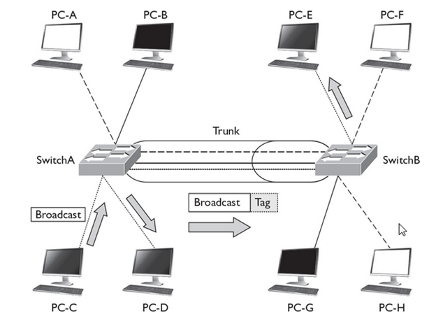
The trunk connection between SwitchA and SwitchB handles traffic for multiple VLANs. A VLAN tagging mechanism is required to differentiate the source of traffic when moving it between the switches. For instance, assume that no tagging mechanism took place between the switches. PC-C generates a broadcast frame, and SwitchA forwards it unaltered to PC-D and then SwitchB across the trunk. The problem with this process is that when SwitchB receives the original Ethernet frame, it has no idea what port or ports to forward the broadcast to, since it doesn’t know the origin VLAN.
As shown in Figure 12-5, SwitchA tags the broadcast frame, adding the source VLAN to the original Ethernet frame (the broadcast frame is tagged). When SwitchB receives the frame, it examines the tag and knows that this is meant only for the VLAN to which PC-E belongs. Of course, since PC-E is connected via an access link connection, SwitchB first strips off the tagging and then forwards the original Ethernet frame to PC-E. This is necessary because PC-E has a standard NIC and doesn’t understand VLAN tagging. Through this process, both switches maintained the integrity of the broadcast domain.
802.1Q trunks support two types of frames: tagged and untagged. An untagged frame does not carry any VLAN identification information in it—basically, this is a standard, unaltered Ethernet frame. The VLAN membership for the frame is determined by the switch’s port configuration: if the port is configured in VLAN 1, the untagged frame belongs to VLAN 1. This VLAN is commonly called a native VLAN. A tagged frame contains VLAN information, and only other 802.1Q-aware devices on the trunk will be able to process this frame.
One of the unique aspects of 802.1Q trunking is that you can have both tagged and untagged frames on a trunk connection, such as that shown in Figure 12-6. In this example, the white VLAN (PC-A, PC-B, PC-E, and PC-F) uses tagged frames on the trunk between SwitchA and SwitchB. Any other device that is connected on this trunk line would need to have 802.1Q trunking enabled to see the tag inside the frame to determine the source VLAN of the frame. In this network, a third device is connected to the trunk connection: PC-G. This example assumes that a hub connects the two switches and the PC together.
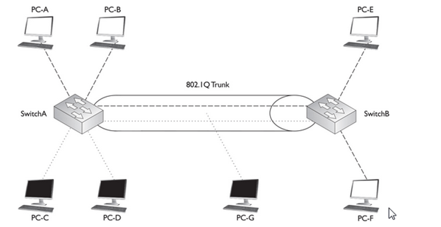
PC-G has a normal Ethernet NIC and obviously wouldn’t understand the tagging and would drop these frames. However, this presents a problem: PC-G belongs to the dark VLAN, where PC-C and PC-D are also members. Therefore, in order for frames to be forwarded among these three members, the trunk must also support untagged frames so that PC-G can process them. To set this up, you would configure the switch-to-switch connection as an 802.1Q trunk but set the native VLAN as the dark one, so that frames from this VLAN would go untagged across it and allow PC-G to process them.PC-G has a normal Ethernet NIC and obviously wouldn’t understand the tagging and would drop these frames. However, this presents a problem: PC-G belongs to the dark VLAN, where PC-C and PC-D are also members. Therefore, in order for frames to be forwarded among these three members, the trunk must also support untagged frames so that PC-G can process them. To set this up, you would configure the switch-to-switch connection as an 802.1Q trunk but set the native VLAN as the dark one, so that frames from this VLAN would go untagged across it and allow PC-G to process them
Frame Format :
As with all ‘open standards’ the IEEE 802.1q tagging method is by far the most popular and commonly used even in Cisco oriented network installations mainly for compatability with other equipment and future upgrades that might tend towards different vendors.
In addition to the compatability issue, there are several more reasons for which most engineers prefer this method of tagging. These include:
- Support of up to 4096 VLANs
- Insertion of a 4-byte VLAN tag with no encapsulation
- Smaller final frame sizes when compared with ISL
Amazingly enough, the 802.1q tagging method supports a whopping 4096 VLANs (as opposed to 1000 VLANs ISL supports), a large amount indeed which is merely impossible to deplet in your local area network.
- As you may have already concluded yourself, the maximum Ethernet frame is considerably smaller in size (by 26 bytes) when using the IEEE 802.1q tagging method rather than ISL. This difference in size might also be interpreted by many that the IEEE 802.1q tagging method is much faster than ISL, but this is not true. In fact, Cisco recommends you use ISL tagging when in a Cisco native environment, but as outlined earlier, most network engineers and administrators believe that the IEEE802.1q approach is much safer, ensuring maximum compatability.
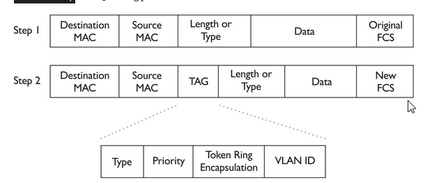
- With the 802.1Q tagging method, the original Ethernet frame is modified. A 4-byte field, called a tag field, is inserted into the header of the original Ethernet frame, and the original frame’s FCS (checksum) is recomputed on the basis of this change.
- The first 2 bytes of the tag are the protocol identifier. For instance, an Ethernet type frame has a protocol identifier value of 0x8100, indicating that this is an Ethernet tagged frame. The next 3 bits are used to prioritize the frame, which is defined in the IEEE 802.1p standard. The fourth bit indicates if this is an encapsulated Token Ring frame (Cisco no longer sells Token Ring products), and the last 12 bits are used for the VLAN identifier (number).
- Shows the process that occurs when tagging an Ethernet frame by inserting the 802.1Q field into the Ethernet frame header. As you can see in this figure, step 1 is the normal, untagged Ethernet frame. Step 2 inserts the tag and recomputes a new FCS value. Below step 2 is a blow-up of the actual tag field. As you can see in this figure, the tag is inserted directly after the source and destination MAC addresse
One advantage of using this tagging mechanism is that, since you are adding only 4 bytes, your frame size will not exceed 1518 bytes, and thus you could actually forward 802.1Q frames through the access link connections of switches, since these switches would forward the frame as a normal Ethernet frame.

Tag protocol identifier (TPID) :
A 16-bit field set to a value of 0x8100 in order to identify the frame as an IEEE 802.1Q-tagged frame. This field is located at the same position as the EtherType field in untagged frames, and is thus used to distinguish the frame from untagged frames.
Tag control information (TCI):
A 16-bit field containing the following sub-fields:
Priority code point (PCP) :
A 3-bit field which refers to the IEEE 802.1p class of service and maps to the frame priority level. Different PCP values can be used to prioritize different classes of traffic.[5]
The Canonical Format Indicator (CFI) bit indicates whether the following 12 bits of VLAN identifier conform to Ethernet or not. For Ethernet frames, this bit is always set to 0. (The other possible value, CFI=1, is used for Token Ring LANs, and tagged frames should never be bridged between an Ethernet and Token Ring LAN regardless of the VLAN tag or MAC address.)
VLAN identifier (VID) :
A 12-bit field specifying the VLAN to which the frame belongs. The hexadecimal values of 0x000 and 0xFFF are reserved. All other values may be used as VLAN identifiers, allowing up to 4,094 VLANs. The reserved value 0x000 indicates that the frame does not carry a VLAN ID; in this case, the 802.1Q tag specifies only a priority (in PCP and DEI fields) and is referred to as a priority tag. On bridges, VID 0x001 (the default VLAN ID) is often reserved for a network management VLAN; this is vendor-specific. The VID value 0xFFF is reserved for implementation use; it must not be configured or transmitted. 0xFFF can be used to indicate a wildcard match in management operations or filtering database entries
