Introduction
Recently, the number of high performance electronic control units (ECU) installed in vehicles has increased significantly. ECUs provide convenient features to drivers,
such as advanced driver assistance systems (ADAS) . Both the number of ECUs for high-performance and the size of the software for reprogramming are increased. This
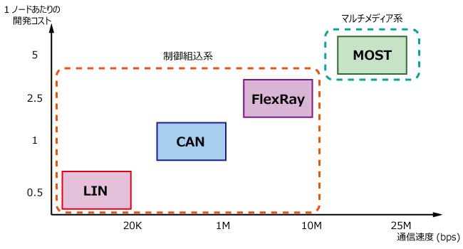
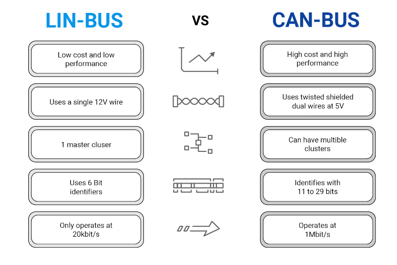
results in the requirement for the network to have a higher bandwidth and provide real-time functionality, but the current CAN-based networks cannot meet these requirements because of a small data size of 8 bytes and low bandwidth of maximum 1 Mbps.
To solve these difficulties, DoIP, which is an Ethernet based diagnostic protocol, was introduced for use in automotive systems. Ethernet can support a maximum data size of 1,500 bytes and with a bandwidth 100 Mbps. Therefore, Ethernet-based DoIP can meet the requirements for high-performance functions. Moreover, automotive systems can provide services, such as diagnosis, calibration and software updates for ECUs, and
new applications that support DoIP through the in-vehicle gateway provide convenience to drivers.
Introduction – DOIP
- The new generation vehicle will provide connectivity and telematics services for enabling vehicle communication. The diagnostic over IP in TCP/IP means enables a connection between diagnostic tool and in-vehicle nodes using IP protocols.
- DoIP facilitates diagnostics related communication between external test equipment’s and automotive control units (ECU) using IP, TCP and UDP.
- Short and simple: “DoIP is the packaging of diagnostic messages in Ethernet frames for communication of a diagnostic tester with a vehicle”
- DoIP is used in combination with the standardized diagnostic protocol UDS (ISO 14229-5: UDSonIP)
- DoIP with Ethernet 100 Base-TX instead of CAN enables substantial higher bandwidth
- In vehicle diagnostics, the diagnostic tools and vehicles are separated by an inter network.
- The DoIP (Diagnostic over IP) standard is used to develop a prototype for vehicle diagnostics
- The main aim of using IP into the family of automotive diagnostic protocol is that the development of new in-vehicle network has led to the need for communication between external test equipment and onboard ECUs using many data link layer technologies.
- DoIP is a protocol mainly used for communication between off-board and on-board diagnostic system
ISO 13400 has been established in order to define common requirements for vehicle diagnostic systems implemented on a Internet Protocol communication link.
ISO 13400 specifies Transport layer, Network layer, Data Link layer and Physical layer for Diagnostics over Internet Protocol (DoIP).
Since the standard Ethernet Physical layer is used as a transmission medium for DoIP, it is also known as Diagnostics over Ethernet.
DoIP with Ethernet 100 Base-TX instead of CAN enables substantial higher bandwidth
DoIP is used in combination with the standardized diagnostic protocol UDS (ISO 14229-5: UDSonIP)
Diagnostics over IP is now readily available and is specified in ISO 13400. It makes no difference which physical layer is used as long as it supports the transmission of IP packets. For example, besides Ethernet, the use of WLAN and UMTS as physical media is also conceivable with DoIP.
The important thing here is that DoIP does not represent a diagnostic protocol according to ISO 13400 but rather an expanded transport protocol. This means that the transmission of diagnostic packets is defined in DoIP, but the contained diagnostic services continue to be specified and described by diagnostic protocols such as KWP2000 and UDS.
A requirement for DoIP is the support of UDP and TCP. UDP is used for transmission of status or configuration information. A TCP connection, on the other hand, enables transmission of actual diagnostic packets via a fixed communication channel. This ensures high reliability of data transmission and enables automatic segmentation of large data packets. TCP and UDP must be implemented in the diagnostic tester as well as in each ECU with DoIP diagnostic capability (DoIP Node) and in each diagnostic gateway (DoIP Gateway or DoIP Edge Node).

As mentioned before, ISO 13400-2 transport layer facilitates diagnostic communication between external test equipment and vehicle electronic components.
- The implementation of a common set of Unified Diagnostic Services (UDS) on Internet Protocol (UDSonIP) is done using ISO 14229-5 Application layer.
- The Vehicle transport layer is facilitated by TCP or UDP. Based on the standard, IPv6 acts a Network Layer and IPv4 can be used for compatibility.
- Ethernet MAC is used as the Data Link Layer. The corresponding Physical Layer for on-board communication is specifies as Broad Reach or 100 Base T, while that for off-board communication is Ethernet.
is DoIP mandatory to use UDS over Ethernet?
UDS defines the Application Layer, but you will need also a Transport Layer – this can be:
- ISO-TP (ISO 15765-2) in case of CAN (UDS on CAN; ISO 14229-3)
- DoIP (ISO 13400-2) in case of Ethernet (UDS on IP; ISO 14229-5)
Using “only UDS” without a Transport Layer is not possible

On the basis of systems architecture:
UDS application layer has been modified to support compatibility with Ethernet transmission medium. This compatibility for UDS on IP is defined by ISO 14229-5 standard.
While the ISO 14229-3 standard defines implementation of UDS on CAN. UDS on IP has DoIP Transport Layer defined by ISO 13400-2 standard. While UDS on CAN has ISO 15765-2 transport layer that support CAN physical layer.
The physical layer for UDS on IP is Ethernet, based on IEEE 802.3, a wired vehicle interface standard and the UDS on CAN is defined by ISO 11898 standard (classical CAN network
On the basis of Data Transmission:
- UDS on IP supports greater latency time of data transmission as compared to CAN.
- A greater bandwidth capacity in DoIP enables it to handle large amount of data in comparison with CAN.
- The standardized data format in DoIP makes the data less prone to error and ideal for diagnostic services.
Why UDS over Ethernet (as DoIP) for next generation automotive applications?
The ever growing complexity of electronic systems and need for large volume of data communication between vehicle networks, meant that automotive OEMs’and Suppliers felt the need for a more effective vehicle communication network like Ethernet.
Case in point: ECU re-programming, remote & on-board diagnostics are some examples of automotive applications that demand for faster data transfer rate.
As Ethernet physical layer doesn’t support bus like structure (like that in CAN), a switch is required for every network node. This ensures that Ethernet based DoIP supports rates of upto 100 mbps as compared to 500 kbps by CAN.
In the past, OEM’s provided diagnostic services over proprietary or KWP protocols. But the trend has shifted to more popular (UDS) protocol that supports various BUS systems such as CAN, K-line, FlexRay and Ethernet.
Hence, UDS is now the most properly used standard for Diagnostic Protocol. DoIP transport layer is defined as a part of the UDS specification.
USE OF DOIP
Retrieving a predefined amount of data from a vehicle without any need for connection establishment or security,
- Quick availability of data that are needed for inspection, maintenance and repair over the IP network without any need for connection establishment or negotiation,
- Programming or updating ECU software with connection establishment and security negotiation,
- Quick availability of all the data that is needed for inspection, maintenance and repair in the assembly line without any need for connection establishment and security negotiation,
- Retrieval of non-diagnostic data, such as address book, e-mail from infotainment components and transferring it to the vehicle or vice versa.
Diagnostic Gateway Implementation
The external diagnostic devices based on DoIP cannot interface directly with in-vehicle networks, so an in vehicle gateway is essential to integrate different in-vehicle networks with Ethernet. As a result, the external diagnostic devices can be connected to the automotive system. The gateway provides an interface to the external diagnostic devices to access the in-vehicle ECUs through an on-board diagnostics (OBD) terminal. If the external diagnostic device is connected to the Internet, the vehicle can provide a range of telematics services from the external diagnostic devices through the gateway.
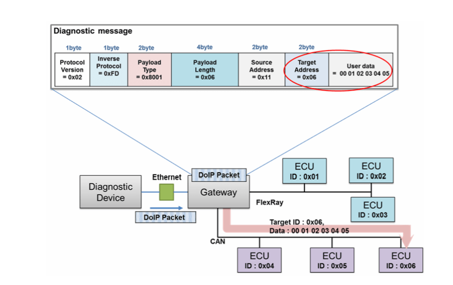
The diagnostic gateway can be connected to the external diagnostic device through the Transmission Control Protocol (TCP), and provides the reliability and integrity of the diagnostic data through the TCP connection. Diagnostic request messages (from the external diagnostic device to the in-vehicle networks) are packed in the TCP datagram and transmitted to the gateway. The diagnostic gateway unpacks the TCP datagram when the TCP packet is received, and separates the diagnostic information (DoIP data type, data length, target address, data payload) into the TCP datagram. Moreover, the
gateway searches the configured routing table that includes a routing parameter, such as the target address, a network type of a target ECU and other network information, and transmits the diagnostic request data to the destination network domain (CAN and FlexRay). The target ECU receives the diagnostic request messages, which perform a diagnostic operation, and transmit a diagnostic response message. The diagnostic
response message is assembled in DoIP format by the diagnostic gateway. A DoIP frame is packed in the TCP datagram, and the diagnostic gateway transmits the TCP
packet to the external diagnostic gateway.
The diagnostic gateway implements the basic operation, such as the connection control, routing activation handler, DoIP header handler and routing of diagnostic messages, and adds additional functions, such as security and a software reprograming.
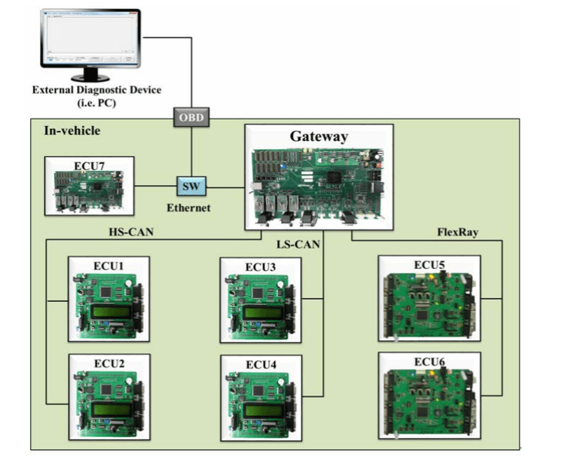
The system consists of the following components: one gateway ECU, two ECUs connected to a High Speed CAN (HS-CAN), two ECUs connected to a Low Speed CAN (LS-CAN), two ECUs connected to a FlexRay network, and on ECU connected to an Ethernet network

Nested header structure
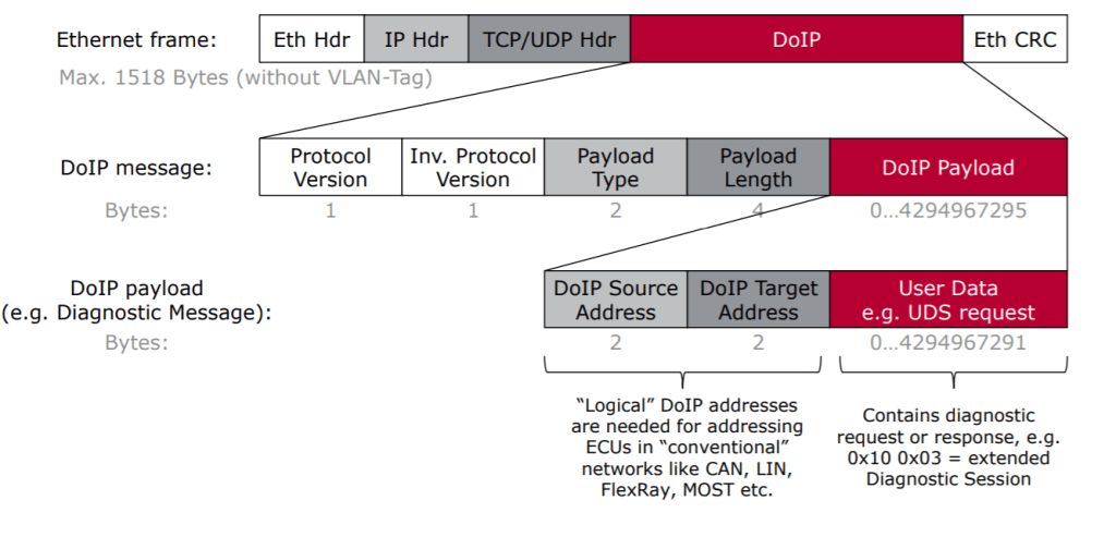
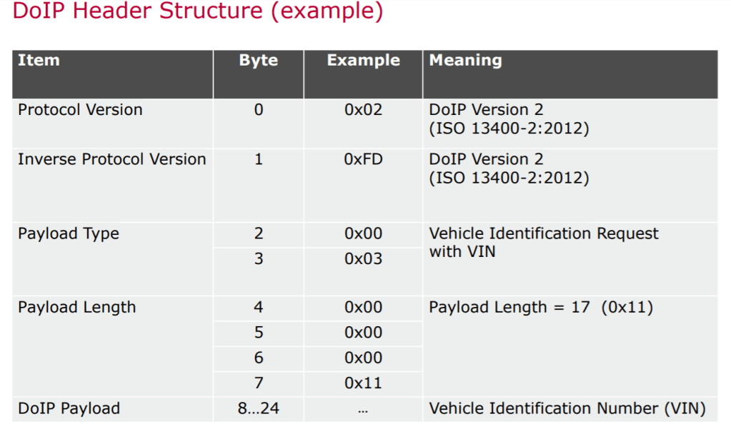
A) The Protocol Version field specifies the version of the DoIP protocol being used, such as 0x01, 0x02, or 0x03. The Inverse Protocol Version field carries the bit inverted value of the Protocol Version, ensuring error-checking during transmission.

B) Payload type :The Payload Type field, represented by two bytes, indicates the type of payload in the message. Multiple payload types are defined, including vehicle identification, diagnostic message delivery, and route activation.

c) The Payload Length field, represented by four bytes, specifies the length of the payload in bytes. It determines the number of data that follows the header section.
d) The DoIP Payload contains the actual data to be transmitted, such as diagnostic messages or control signals. The structure of the payload depends on the Payload Type specified in the header. Within the payload, the Identifier field is used to identify the sender and receiver of the message, providing Source Address and Target Address subfields.
The DoIP module can manage the active connection between the external diagnostic device and the gateway, and it routes the diagnostic messages between the external
diagnostic device and the in-vehicle networks. presents the process for routing the diagnostic message to the target ECU from the external diagnostic device. The
gateway receives the DoIP request messages from the external diagnostic device, and the received DoIP request messages are delivered to the DoIP module through the
TCP/IP stack. The DoIP module separates the protocol version, payload type, and payload length in the DoIP frame, and then checks the target ECU address in the DoIP payload. Finally, the diagnostic user data in the DoIP payload is transmitted to the network domains connected to the target ECU.
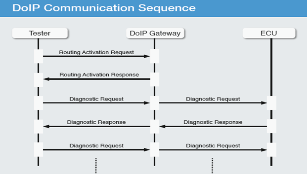
Diagnostics process
During diagnosis, the diagnostic gateway first receives the request from the tester. The request contains the diagnostic packet with the desired diagnostic service and the logical address of the ECU to be diagnosed. The gateway then removes the diagnostic packet and packs it into a message that can be sent on the utilized bus system or network. For example, if an ECU is to be addressed using CAN, the gateway sends out a message with the associated identifier (e.g., 0x600) to this bus. It then waits for a response from the ECU. As soon as the response is received from the associated bus system or network (e.g., CAN with identifier 0x700), the gateway returns the response for the original diagnostic service to the tester. For this, it adds the logical address of the ECU so that the tester can uniquely assign the response. This allows a tester to send requests for multiple ECUs to different bus systems and networks without waiting for a sequential response.


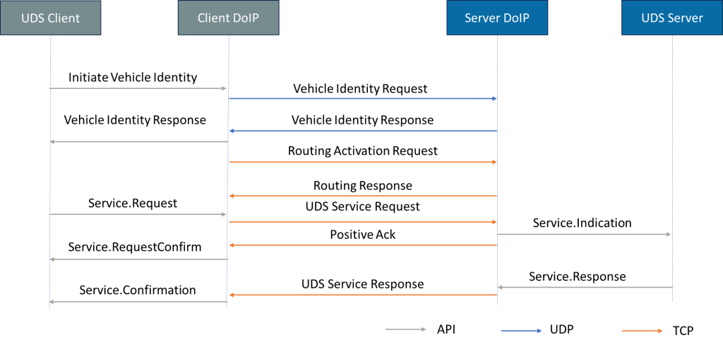
Let’s explore the step-by-step communication flow involved in establishing a connection between the user test equipment and the DoIP entity in the vehicle.
1.Opening a UDP Socket: The initial step is to open a UDP socket with the destination port (13400). This socket allows communication between the client and server.
2. Vehicle Identity Request: The client sends a vehicle identity request to the server DoIP, seeking information about the vehicle’s identification. This request helps establish a connection between the client and the vehicle.
3. Vehicle Identity Response: The server DoIP responds to the vehicle identity request by providing the necessary information, such as VIN (Vehicle Identification Number), GID (Global Identifier), EID (Entity Identifier), and logical address.
4. Opening a TCP Connection: After receiving the vehicle identity response, the client opens a TCP connection over the TCP_DATA port. From this point forward, all further messages are exchanged via this TCP socket.
5 Routing Activation Request: To enable routing on the initialized connection, the client sends a routing activation request message to the DoIP server. This request indicates the client’s eligibility and the desire to activate routing.
6.Routing Activation Response: If the client is eligible and there are fewer active connections registered, the server responds with a routing activation response. This response confirms that the routing has been successfully activated, allowing the client to send valid DoIP messages, such as diagnostic messages.
7. DoIP Header Handler: The DoIP entity executes the DoIP header handler upon receiving any type of data. If the payload contains a diagnostic message (identified by payload type 0x8001 in the generic DoIP header), the diagnostic message handler is called to process the payload.
8. Diagnostic Message Handler: The diagnostic message handler parses the received request, filters the required data for the UDS request based on the service ID and identification, and forwards it to the UDS protocol handler. This handler plays a crucial role in processing diagnostic requests and generating appropriate responses.
9.Diagnostic Response: Once the diagnostic response is formed, the ECU transmits it to the user test equipment. This response contains the requested data or information related to the diagnostic process.
This communication flow ensures a seamless exchange of information between the client and server, allowing for effective diagnostic processes and troubleshooting.
Refrences:
https://avtoad.com.ua/en/base/ethernet-doip-diagnostic-protocol