Introduction
An automobile as we know it was not invented in a single day by a single inventor. It is more than an engine and a body; it is a complex machine that has undergone over a century of evolution Detecting a failure in this complex machine would be a tedious task. However, most of the vehicles today include computers (Electronic Control Unit (ECU)), which monitors several sensors, located throughout the engine, fuel and exhaust systems. When the computer system of the car detects a fault, two things are supposed to happen/monitored. First, a warning light on the dashboard is set, to inform the driver that a problem exists. Second the code is recorded in the computer’s memory (Electrically Erasable Programmable Read-Only Memory) so that it can later be retrieved by a technician for diagnosis and repair.
When the Check Engine Light comes on, a diagnostic trouble code (DTC) is recorded in the on-board computer memory that corresponds to the fault. Some problems can generate more than one trouble code, and some vehicles may have multiple problems that set multiple trouble codes.
Engine/Electronic Control Unit (ECU)
The ECU can refer to a single module or a collection of modules. These are the brains of the vehicle. They monitor and control many functions of the car. These can be standard from the manufacturer, reprogrammable, or have the capability of being daisy-chained for multiple features. Tuning features on the ECU can allow the user to make the engine function at various performance levels and various economy levels. On new cars, these are all typically microcontrollers.
Some of the more common ECU types include:
• Engine Control Module (ECM) – This controls the actuators of the engine, affecting things like ignition timing, air to fuel ratios, and idle speeds.
• Vehicle Control Module (VCM) – Another module name that controls the engine and vehicle performance.
• Transmission Control Module (TCM) – This handles the transmission, including items like transmission fluid temperature, throttle position, and wheel speed.
• Powertrain Control Module (PCM) – Typically, a combination of an ECM and a TCM. This controls your powertrain.
• Electronic Brake Control Module (EBCM) – This controls and reads data from the anti-lock braking system (ABS).
• Body Control Module (BCM) – The module that controls vehicle body features, such as power windows, power seats, etc.
What is Vehicle Diagnostics ?
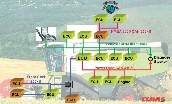
Modern vehicles are packed full of modules, all continuously monitoring themselves and reporting their status.
Detecting a failure in this complex machine would be a tedious task. However, most of the vehicles today include computers (Electronic Control Unit (ECU)), which monitors several sensors, located throughout the vehicle.
When the computer system of the car detects a fault, two things are supposed to happen/monitored.
First, a warning light on the dashboard (MIL – Malfunction Indication Light) is set, to inform the driver that a problem exists.
Second the code is recorded in the computer’s memory (EEPROM) so that it can later be retrieved by a technician for diagnosis and repair.
Diagnostics, as the word suggests, is to identify the cause of a problem or a situation. Whenever the ECU finds a problem, it stores that problem as a Diagnostics Trouble Code (DTC) in the ElectricallyErasableProgrammableRead-OnlyMemory (EEPROM) for later retrieval.
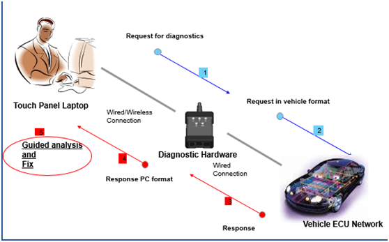
A diagnostic equipment allows you to diagnose and fix the problem with the vehicle. Diagnostic Tools are used to read data (DTC’s) from the EEPROM to analyze the cause of failure.
Such an equipment will communicate with the vehicle and for this, it requires basically a communication medium and a communication protocol
Malfunction Indicator Lamp (MIL)
The MIL is that terrible little light in the dash that indicates a problem with the car. There are a few variations, but they all indicate an error found by the OBD-II protocol.
Vehicle Communication Interfaces (VCI)
VCI provide an interface between a vehicle’s onboard diagnostics link (e.g. OBD) and a diagnostic application
▪ Features
▪ Enable communication between offboard device and ECU
via multiple communication protocol
– Supports ECU reprogramming
.
Diagnostics Protocol
Protocol refers to a set of rules for communication. Here the communication happens between two ECU’s which follow the same rule and able to exchange the information. The protocols which are used for Diagnostics purposes are known as Diagnostics Protocol. The automotive industry has come up with Diagnostics protocols which are used for diagnostics purposes like, CAN (Control Area Network), K-Line, UDS (Unified Diagnostics Services), and KWP (Keyword Protocol) and so on.
Diagnostics Session
Diagnostic session is the basis for/of communication between the ECU and the diagnostic tool. During ‘Diagnostics’ the ECU being analyzed is in a particular session. Basically there are different types of diagnostics sessions like Default Session, Extended Diagnostic Session and ECU Programming Session. After Ignition on, ECU will be switched to a Default Diagnostic Session and after receiving the request from Diagnostic Tool, the ECU will be switched to the Extended Diagnostic Session. Further, after receiving the ECU Programming Session start request from Diagnostic tool, it will switch to the ECU Programming Session.
Diagnostic Trouble Codes
Diagnostic Trouble Codes or OBD2 Trouble Codes are codes that the car’s OBD system uses to notify you about an issue. Each code corresponds to a fault detected in the car. When the vehicle detects an issue, it will activate the corresponding trouble code.
A vehicle stores the trouble code in it’s memory when it detects a component or system that’s not operating within acceptable limits. The code will help you to identify and fix the issue within the car.
Each trouble code consists of one letter and four digits, such as P1234
Format of the OBD2 Trouble Codes
The OBD2 Trouble Codes are categorized into four different systems.
- Body (B-codes) category covers functions that are, generally, inside of the passenger compartment. These functions provide the driver with assistance, comfort, convenience, and safety.
- Chassis (C-codes) category covers functions that are, generally, outside of the passenger compartment. These functions typically include mechanical systems such as brakes, steering and suspension.
- Powertrain (P-codes) category covers functions that include engine, transmission and associated drive train accessories.
- Network & Vehicle Integration (U-codes) category covers functions that are shared among computers and systems on the vehicle.
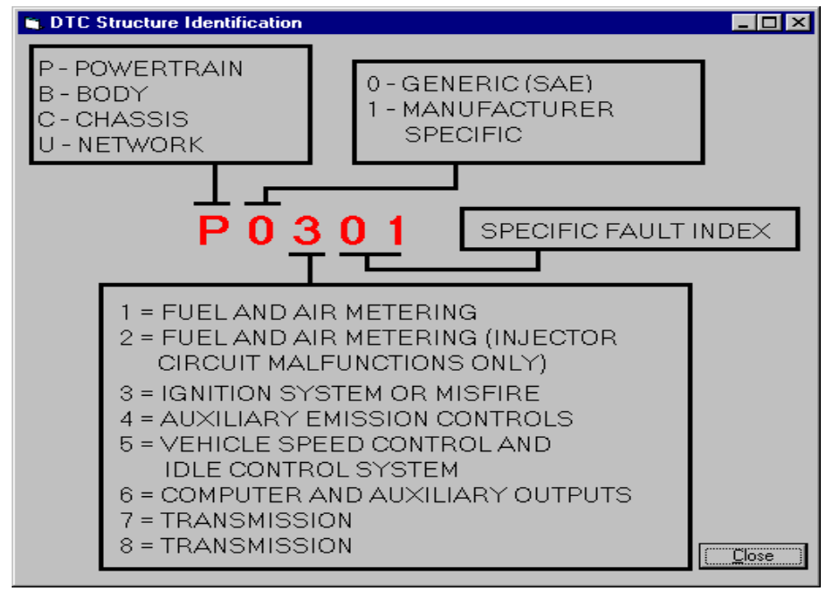
Generic and manufacturer specific codes
The first digit in the code will tell you if the code is a generic or manufacturer specific code.
Codes starting with 0 as the first digit are generic or global codes. It means that they are adopted by all cars that follow the OBD2 standard. These codes are common enough across most manufacturers so that a common code and fault message could be assigned.
Codes starting with 1 as the first digit are manufacturer specific or enhanced codes. It means that these codes are unique to a specific car make or model. These fault codes will not be used generally by a majority of the manufacturers.
What is OBD?
- OBD stands for “On-Board Diagnostics.” It is a computer-based
system originally designed to reduce emissions by monitoring the performance of
major engine components.
- A basic OBD system consists of an ECU (Electronic Control Unit), which uses input from various sensors (e.g., oxygen sensors) to control the actuators (e.g., fuel injectors) to get the desired performance. The “Check Engine” light, also known as the MIL (Malfunction Indicator Light), provides an early warning of malfunctions to the vehicle owner
On-Board Diagnostics (OBD) is your vehicle’s built-in self-diagnostic system
- Indicates when there’s an error via the ‘malfunction indicator light’
- Allows a mechanic (or you) to troubleshoot by scanning for Diagnostic Trouble Codes (DTCs)
- OBD2 runs on CAN bus in majority of vehicles today
- The OBD2 system can be accessed via an OBD2 16-pin connector found within 0.61m of the steering wheel.
OBD System Gives Vehicle Technician Access to Health Information for Vehicle Sub System
Standards specified by OBD
- Type of diagnostic connectors and pin-out
- Protocols supported
- Messaging format
How OBD II Works
- Modern Electronics With Self Diagnosis supports The Technician by Registering actual Values ,comparing Them with Nominal Values & Diagnosing Faults that are Stored for Repair Purpose
- There are many sensors throughout your car: oxygen sensors, engine knock sensors, manifold pressure sensors and so on and so on. Each one of these sensors sends a signal to your car’s computer the Engine Control Unit (ECU). The ECU uses that information to adjust different elements of your engine operation, the fuel injection or the spark timing for example.
- During the Operating Time of The vehicle ECU’s are Constantly checking the sensors they are connected to.By Comparing the Measured Values and Stored data an ECU is able to Determine whether Measured Values exceed or still within Tolerance Required
- If the information that the ECU gets from one of its sensors is too far out of whack, it saves a code called a Diagnostic Trouble Code (DTC). It also sends a signal to you check engine light. If the light comes on and stays on, then you have a minor problem
- This Fault Memory can be Read Later in workshop and Provide Valuable information for The Technician.
OBD communication protocols
- OBD regulations are defined by a series of SAE/ISO standards, that describe in detail how certain OBD functions need to be implemented on the ECU side, and how the
communication between the ECU and the diagnostic tool is going to be performed.
- OBD-2 (US) regulations are described in SAE standards,
EOBD (EU) regulations are described in ISO standards.
- The OBD communication protocol can be regarded as an OSI (Open Systems Interconnection) model, with several layers, each defined in a standard:
- OBD means also data exchange between vehicle and external equipment (scantool). This can be done using on of the following protocols:
| Protocol | Description |
| SAE J1850 PWM | Pulse Width Modulation used mainly by Ford Motor Company data transfer speed 41.6 kBaud/s uses two wires for data transmission |
| SAE J1850 VPW | Variable Pulse Width used mainly by General Motors data transfer speed between 10.4 and 41.6 kBaud/s uses two wires for data transmission |
| ISO 9141-2 | Used mainly by Chrysler, European and Asian vehicle manufacturers data transfer speed 10.4 kBaud/s. uses only one wire for data transmission (K-line), the second line (L-line) is optional |
| ISO 14230 (KWP2000) | KeyWord Protocol similar with ISO 9141-2 data transfer speed between 1.2 and 10.4 kBaud/s. uses only one wire for data transmission (K-line), the second line (L-line) is optional |
| ISO 15765 (CAN) | Controller Area Network starting with 2008 all new vehicles sold in USA must use CAN as OBD communication protocol starting with Euro 4 most of the vehicles sold in EU use CAN as OBD communication protocol data transfer speed between 250 and 500 k Baud/s uses two wires for data transmission (CAN-high and CAN-low) |
On-Board Diagnostics (OBD) – introduction to the Modes of Operation (Diagnostic Services)
- OBD modes of operation (also called diagnostic
services) define how the data is requested from the vehicle and how the vehicle
responds to the request. You can look at the OBD modes of operation as a
definition of the “language” to be used by both parties (scan tool and vehicle)
when requesting and sending data.
- The diagnostic Service can be defined as an information exchange initiated by a
client (external test equipment) in order to require diagnostic information
from a server (ECU) or/and to modify its behaviour for diagnostic purpose.
- In the OBD CAN protocol there are 9/10 modes of
operation (diagnostic services), each defined by an identifier (also called
header). First 9 modes of operation are common between ISO and SAE standards,
the 10th is specific to the SAE standard.
The communication between diagnostic device (scantool) and vehicle is client-server type, based on request and response.
The Client is defined as the function that is part of the diagnostic device (scantool, tester), that makes use of the diagnostic services .
The Server is defined as a function that is part of an electronic control unit on-board of the vehicle and that provides data to the diagnostic services.
The diagnostic Service can be defined as an information exchange initiated by a client (external test equipment) in order to require diagnostic information from a server (ECU) or/and to modify its behavior for diagnostic purpose.
The table below describes the purpose of each mode of operation (diagnostic service) and which standard contains it
| Diagnostic service Mode of operation | Description | Standard |
| $01 | Request Current Powertrain Diagnostic Data | SAE, ISO |
| $02 | Request Powertrain Freeze Frame Data | SAE, ISO |
| $03 | Request Emission-Related Diagnostic Trouble Codes | SAE, ISO |
| $04 | Clear/Reset Emission-Related Diagnostic Information | SAE, ISO |
| $05 | Request Oxygen Sensor Monitoring Test Results | SAE, ISO |
| $06 | Request On-Board Monitoring Test Results for Specific Monitored Systems | SAE, ISO |
| $07 | Request Emission-Related Diagnostic Trouble Codes Detected During Current or Last Completed Driving Cycle | SAE, ISO |
| $08 | Request Control of On-Board System, Test or Component | SAE, ISO |
| $09 | Request Vehicle Information | SAE, ISO |
| $0A | Request Emission-Related Diagnostic Trouble Codes with Permanent Status | SAE |
The dollar sign “$” in front of the numerical value highlights that this is an identifier. It’s important to know that the numerical values of the identifiers are in hexadecimal format
OBD2 PIDS & MESSAGES EXPLAINED:
In simplified terms, an OBD2 message is comprised of an identifier and data.
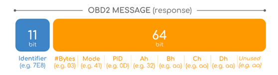
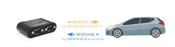
An example of a request/response CAN message for the PID ‘Vehicle Speed’ with a value of 50 km/h can look like this:
Request: 7DF 02 01 0D 55 55 55 55 55
Response: 7E8 03 41 0D 32 aa aa aa aa
- (Here the 32 is the hexadecimal value of 50).
- IDENTIFIER: For OBD2 messages, the identifier is standard 11-bit and used to distinguish between “request messages” (ID 7DF) and “response messages” (ID 7E8 to 7EF). Note that 7E8 will typically be where the main engine or ECU responds at.
- LENGTH: This simply reflects the length in number of bytes of the remaining data (03 to 06). For the Vehicle Speed example, it is 02 for the request (since only 01 and 0D follow), while for the response it is 03 as both 41, 0D and 32 follow.
- MODE: For requests, this will be between 01-0A. For responses the 0 is replaced by 4 (i.e. 41, 42, … , 4A). There are 10 modes as described in the SAE J1979 OBD2 standard. Mode 1 shows Current Data and is e.g. used for looking at real-time vehicle speed, RPM etc. Other modes are used to e.g. show or clear stored diagnostic trouble codes and show freeze frame data.
- PID: For each mode, a list of standard OBD2 PIDs exist – e.g. in Mode 01 PID 0D is Vehicle Speed. For the full list, check out the aforementioned Wikipedia OBD2 PID overview. Each PID has a description and some have a specified minimum/maximum and conversion formula.
- The formula for speed is e.g. simply A, meaning that the Ah data byte (which is in HEX) is converted to decimal to get the km/h converted value (i.e. 32 becomes 50 km/h above). For e.g. RPM (PID 0C), the formula is (256*A + B) / 4.
- Ah, Bh, Ch, Dh: These are the data bytes in HEX, which need to be converted to decimal form before they are used in the PID formula calculations. Note that the last data byte (after Dh) is not used.
HOWTO LOG OBD2 DATA?
- OBD2 data logging works as follows:
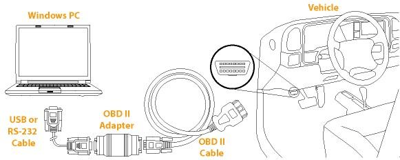
- You connect a OBD2 scanner or OBD2 data logger to the OBD2 16 pin connector
- Via the tool, you enter “request messages” (queries) transmitted via the CAN-bus
- The relevant ECUs react and send “response messages” via the CAN-bus
When you attach an OBD-II scan tool, it sends specially formatted diagnostic command messages over the CAN bus. Nodes on the network that can output diagnostic information are listening for these messages, and send out the requested status information over CAN when asked. For example the technician enters Mode 1 (query the real time state of the car, meaning your car needs to be started) PID 0D (query for vehicle speed) into the scan tool, and the scan tool sends the corresponding message over the CAN bus, and the engine control unit that knows the vehicle speed returns the vehicle speed (the response format is defined by OBD-II PIDs at http://en.wikipedia.org/wiki/OBD-II_PIDs), and the scan tool displays the vehicle speed on the tool’s screen.
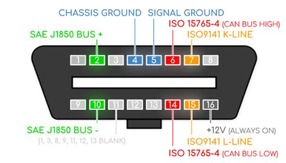
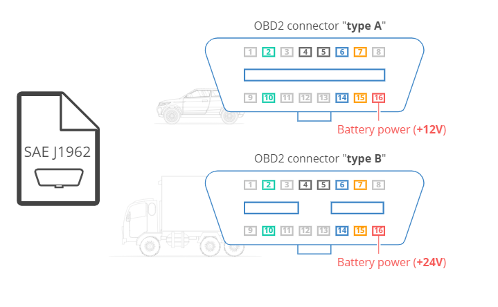
THE OBD-2 CONNECTOR
The OBD2 standard (SAE J1962) specifies two female OBD2 16-pin connector types (A & B). Below is an example of a Type A OBD2 pin connector (also sometimes referred to as the Data Link Connector
Exploring the Scope of Off-board Diagnostics in the Vehicle
Off-board vehicle diagnostics takes care of the diagnostics of every other vehicle ECU function other than emission. There are several protocol standards defined for off-board diagnostics, however,
Unified Diagnostics Services (UDS) is the most popular diagnostic protocol. The diagnostics manager of the UDS protocol stores every issue as fault codes called Diagnostics Trouble Code (DTC). When a vehicle is running, the off-board diagnostics is also active. However, the contrast with on-board diagnostics lies in the reporting part.
In case of OBD, the fault is communicated to the information cluster by triggering the Malfunction indicator light. Whereas, in the off board diagnostics, no such instant reporting is carried out. The issue is stored in the EEPROM part of the vehicle ECU for retrieval at the service garage using a vehicle diagnostic testing tool.
However, the scope of off-board diagnostics (UDS) is not limited to just storing the diagnostic trouble codes (DTCs). It is capable of offering services such as vehicle ECU reprogramming, remote routine activation, writing data on the automotive Electronic Control Unit and even more.
This is one of the major aspects that differentiates on-board and off board vehicle diagnostics. When the UDS stack is integrated to the vehicle ECU, the UDS services are configured to it. These configurations are mostly OEM specific. It means that a tester tool authorized by the same automotive OEM can only read or write data from the vehicle ECU. Unlike the OBD 2, any after-market tester tool will not work.
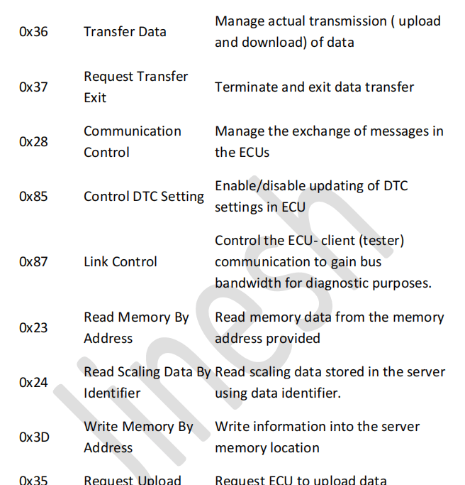
Services
As UDS has been accepted by many automotive OEMs as the de facto Off-board diagnostics, its services are very important. We have compiled them here:
UDS Services Description
0x10 Diagnostic Session Enable various diagnostics sessions Control within ECU
0x11 ECU Reset Resetting the ECU to be back in the default session
0x27 Security Access Limit access to data and services to prevent unauthorized access
0x3E Tester Present Alert the ECU(s) that client is still connected so that diagnostic sessions remain active.
0x22 Read Data By Identifier Request data from ECU(s)
0x2E Write Data By Identifier Write data onto ECU(s)
0x14 Clear Diagnostic Information Clear diagnostic trouble codes (DTC) stored in the ECU
0x19 Read DTC Information Read DTC from the ECU
0x2F Input Output Control By Identifier Control the input/output signals through the diagnostic interface
0x31 Routine Control control all the routine services (erasing memory, testing routines etc.)
0x34 Request Download Request ECU to initiate download session based on request from the tester
On-board Vs Off-board Vehicle Diagnostics: A Quick Comparison
scope and services of both on-board and off-board vehicle diagnostics should be clear by now. Emission being a very crucial aspect of a vehicle, on-board diagnostics is completely dedicated to it. The strict CARB and EURO emission guidelines call for real-time monitoring of emission related parameters. The Malfunction Indicator light is also associated with the on-board diagnostics, implying the urgency an emission related issue requires. The off-board vehicle diagnostics, on the other hand, may not require enough urgency to light up an MIL. However, it has many other roles to play. Its comprehensive set of services help the garage personnel perform tests, run routines, update the ECU, write data and much more.
The crux of the story is that both on-board and off-board systems perform diagnostics and have their scope clearly demarcated by their services. While one takes care of the emission the other handles everything other than that
The difference between UDS and OBD protocols
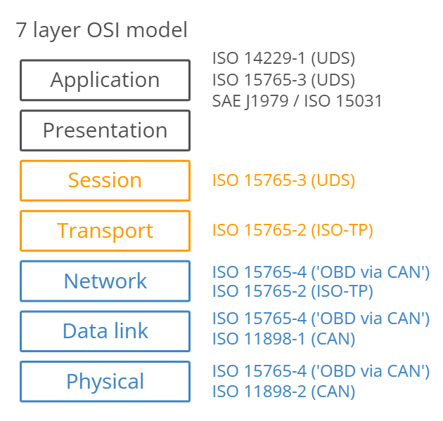
UDS (Unified Diagnostic Services) is a diagnostic communication protocol in the electronic control unit (ECU) environment within the automotive electronics. It is similar to ISO 14230-3 (KWP2000) and ISO 15765-3 (Diagnostic Communication over Controller Area Network (DoCAN)). The protocol is “unified” in the sense that it is used internationally across different companies and manufacturers. UDS differs from the CAN protocol in a crucial way. The CAN protocol specifies the first and second layer of the OSI Model – that is the Physical Layer (ISO 11898-2) and the Data Link Layer (ISO 11898-1). UDS, however, also specifies the fifth (Session Layer) and seventh (Application Layer) layers of the OSI Model.
OBD (On-board diagnostics) is an automotive term referring to a vehicle’s self-diagnostic and reporting capability. OBD systems give the vehicle owner or repair technician access to the status of the various vehicle subsystems.
It is used to implement vehicle diagnostics communication for diagnosis and repair of vehicle sub-systems through communication with Electronic Control Units (ECU). ECUs monitor and control the sub-systems of a vehicle. Common ECUs include Engine Control Module (ECM), Transmission Control Module (TCM), Electronic Brake Control Module (EBCM), etc. Thus OBD helps to detect and control engine failures, performance issues and fight vehicle emission.
Generally, UDS and OBD are both diagnostic protocol, but they are actually not comparable. While UDS protocol is used to diagnose a fault in an off-board condition, i.e. when the car is at the service center, OBD is essentially an onboard diagnostic service.
Link between OBD2 and CAN bus
On board diagnostics, OBD2, is a ‘higher layer protocol‘ (like a language). CAN is a method for communication (like a phone).
In particular, the OBD2 standard specifies the OBD2 connector, incl. a set of five protocols that it can run on (see below). Further, since 2008, CAN bus (ISO 15765) has been the mandatory protocol for OBD2 in all cars sold in the US.
What is the ISO 15765 standard?
ISO 15765 refers to a set of restrictions applied to the CAN standard (which is itself defined in ISO 11898). One might say that ISO 15765 is like “CAN for cars”.
In particular, ISO 15765-4 describes the physical, data link layer and network layers, seeking to standardize the CAN bus interface for external test equipment. ISO 15765-2 in turn describes the transport layer (ISO TP) for sending CAN frames with payloads that exceed 8 bytes. This sub standard is also sometimes referred to as Diagnostic Communication over CAN (or DoCAN). See also the 7 layer OSI model illustration.

So This was Brief Introduction to Diagnostics in Next Blog we will learn about CAN Protocol.
