What is Unified Diagnostic Service (UDS) Protocol?
With rapid implementation of electronic embedded systems in vehicles, the need to track and control the vehicle’s different parameters was imperative. Thus, diagnostic systems were developed so that the clients (designers, testers, and mechanics) could detect the faults in the vehicle by connecting their diagnostic tester tool to the electronic control units (ECUs) in the vehicle.
Unified Diagnostic Service (UDS) is an automotive protocol that lets the diagnostic systems communicate with the ECUs to diagnose faults and reprogram the ECUs accordingly (if required).
UDS is called “Unified” because it combines and consolidates standards such as KWP 2000 (ISO 14230) or Diagnostics on CAN (ISO 15765) and is independent of vehicle manufacturers.
ISO-14229 Standards Available:
ISO-14229 consists of the following parts, under the general title Road vehicles — Unified diagnostic services (UDS):
ISO 14229-1: Specification and requirements.
ISO 14229-2: Session layer services.
ISO 14229-3: Unified diagnostic services on CAN implementation (UDSonCAN).
ISO 14229-4: Unified diagnostic services on FlexRay implementation (UDSonFR).
ISO 14229-5: Unified diagnostic services on Internet Protocol implementation (UDSonIP).
ISO 14229-6: Unified diagnostic services on K-Line implementation (UDSonK-Line).
Need for UDS Protocol for Vehicle Diagnostics
As OEM’s integrate/assemble automotive ECU and components from different suppliers, a need for a standard diagnostic protocol was felt.
This is because, prior to a Unified Protocol OEMs’ and suppliers had to deal with compatibility issues between different diagnostic protocols like KWP 2000, ISO 15765, and diagnostics over K-Line.
Unified Diagnostic Service (UDS) is the preferred choice of protocols for all the off-board vehicle diagnosis. Off-board diagnostics refers to the diagnostics of the vehicle parameters when the car is at servicing in the garage (when the car is stationary).
ECU flashing and reprogramming can also be performed efficiently with the help of UDS protocol stack.
Also, UDS protocol is quite flexible and is capable of performing more detailed diagnostics as compared to other protocols like OBD and J1939.
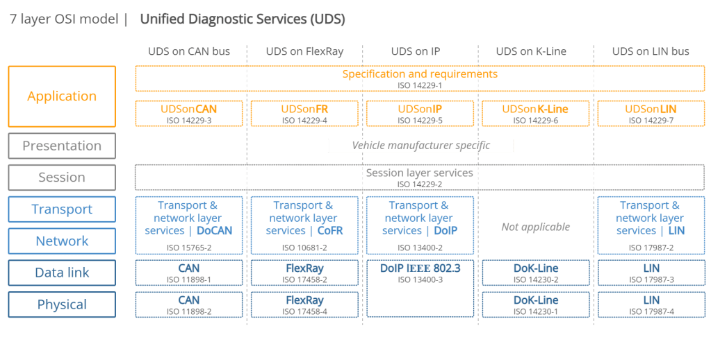
Implementation of UDS on CAN in OSI model
The diagnostic tool contacts all control units installed in a vehicle, which have UDS services enabled. In contrary to the CAN protocol, which only uses the first and second layers of the OSI Model, UDS services utilize the fifth and seventh layers of the OSI model.
The messages defined in UDS can be sent to the controllers which must provide the predetermined UDS services. This makes it possible to inteograte the fault memory of the individual control units or to update them with a new firmware.
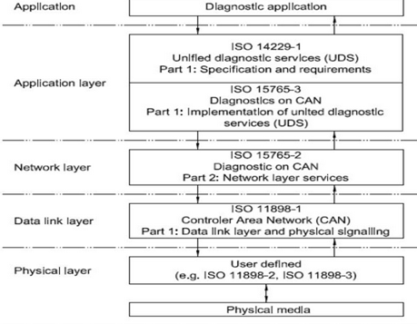
- ISO 14229-1 has been established in order to define common requirements for diagnostic systems, whatever the serial data link is.
- ISO 15765-2, or ISO-TP is an international standard for sending data packets over a CANBus.
– The protocol allows for the transport of messages that exceed the eight byte maximum payload of CAN frames.
– ISO-TP segments longer messages into multiple frames, adding metadata that allows the interpretation of individual frames and reassembly into a complete message packet by the recipient.
– It can carry up to 4095 bytes of payload per message packet.
What is the difference between UDS protocol and OBD protocol?
Although UDS and OBD2 are both diagnostic protocol, they are actually not comparable. While UDS protocol is used to diagnose fault in an off-board condition, i.e. when the car is at the service center, OBD is essentially an on-board diagnostic service.
However, I will try to draw some comparison to clear the air.
1. OBD2 is essentially used for emission related diagnosis of the vehicle which implies that it interacts only with those ECUs that control emission.
UDS Protocol on the other hand is ideal for both emission and non-emission related diagnosis.
2. The next difference is in terms of layers. OBD 2 has 4 layers viz. application layer, transport layer, data link layer, and the physical layer.
UDS protocol is defined in the ISO 14229 standard. It is the application layer of the OSI reference model and is independent of the bus-system. The protocols for specific bus-systems like CAN and K-Line etc. are defined in separate standards viz. ISO 15765-3 (CAN). This way, the OEMs are not bound to use any specific communication system in the vehicle.
The messages and data in OBD2 are defined in the protocol and cannot be modified by the OEMs. However, UDS protocol gives the OEMs the liberty to specify how they define the data as well as the parameters.
Physical and functional addressing:
There is a possibility for the diagnostic tester (client) to send physical or functional UDS-requests. A functional request is a broadcast-type message which will be sent to all ECU:s which are on the CAN-network. Physical the UDS-requests are only sent to a single ECU on the network. Suppose already you know in which module or ECU the faults are happening, then the diagnostic engineer in the service center can directly connect to that ECU to send the diagnostic request (Physical addressing) and read the diagnostic data and fix the issue. If the engineer don’t know where is the fault happening obviously he will be sending the request (Functional addressing) globally to all the ECU available in the vehicle, read all the active DTC and fix it.
UDS Diagnostic Frame Format:
Since the UDS protocol is working on the CAN protocol so that the maximum 8-bytes of the data can be requested and get to the response in a message. Like CAN protocol, in UDS protocol, there are 2-types of the frames are available.
1. Diagnostic request Frame (With/without Sub-function-ID).
2. Diagnostic Response Frame.
Again the Response frame is divided into two types as:
Positive Response.
Negative Response
UDS Protocol Request Frame Format:
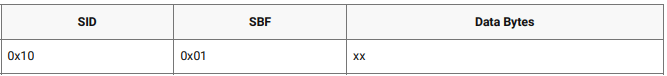
Whenever the client wants to request anything from the data then the tester will send this request the frame to get the response from the server on the CAN data field. This frame had consisted of 3 fields as:
Service ID. Sub-Function ID (optional: not exist for some diag. services).
Data bytes.
NOTE: D1=BIT7(POSRESPONSEINDICATIONBIT) +SUB-FUNCTION ID(BIT0…BIT6)
if Bit7=True; Then No response is required.
if Bit7=False; Then the response required
UDS Protocol Response Frame Format:
Whenever a diagnostic engineer or tester will request any service to a vehicle, there is a possibility of two types of response from the vehicle or from a particular ECU as per physical or functional request type.
Positive Response Frame Format:
Whenever the tester will request to the server if it is correct and the server has been executed the request successfully, then it will send to the response message with respect to this request by the adding 0x40 to the respective service ID for the reference. Positive response 1st byte should be Request Service ID + 0x40.
onse frame else it will be a -Ve response message with Negative Response Code (NRC)
UDS message structure
UDS is a request based protocol. In the illustration we’ve outlined an example of an UDS request frame (using CAN bus as basis):

#1 Protocol Control Information (PCI)
The PCI field is not per se related to the UDS request itself, but is required for diagnostic UDS requests made on CAN bus. In short, the PCI field can be 1-3 bytes long and contains information related to the transmission of messages that do not fit within a single CAN frame. We will detail this more in the section on the CAN bus transport protocol (ISO-TP).
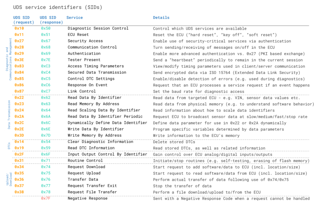
#2 UDS Service ID (SID)
The use cases outlined above relate to different UDS services. When you wish to utilize a specific UDS service, the UDS request message should contain the UDS Service Identifier (SID) in the data payload. Note that the identifiers are split between request SIDs (e.g. 0x22) and response SIDs (e.g. 0x62). As in OBD2, the response SIDs generally add 0x40 to the request SIDs.
#3 UDS Sub Function Byte
The sub function byte is used in some UDS request frames as outlined below. Note, however, that in some UDS services, like 0x22, the sub function byte is not used.
Generally, when a request is sent to an ECU, the ECU may respond positively or negatively. In case the response is positive, the tester may want to suppress the response (as it may be irrelevant). This is done by setting the 1st bit to 1 in the sub function byte. Negative responses cannot be suppressed.
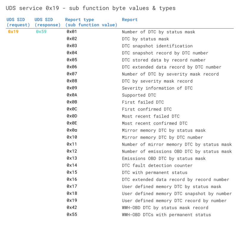
The remaining 7 bits can be used to define up to 128 sub function values. For example, when reading DTC information via SID 0x19 (Read Diagnostic Information), the sub function can be used to control the report type – see also below table.
Negative Response Frame Format:
If the client did not request in a proper frame format or the server is not able to execute the request due to the internal problem, then it will send the negative response to the client. Negative response 1st byte should be 0x7F. Negative response 2nd byte should be Service ID. Negative response 3rd byte should be Response Code.
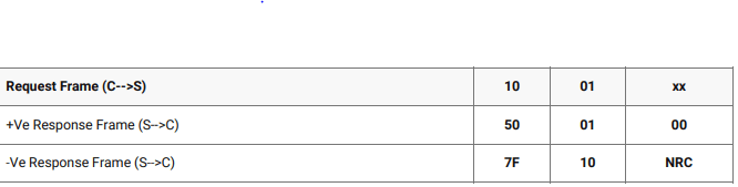
In the above table i have give a demo request and response message format. Like this if any diagnostic data needed the tester can request from his computer to the vehicle or you can say a particular ECU to get the data as response message. If the request will received by the ECU or server successfully and executed also with all the preconditions then the ECU or server will send the message with +Ve resp
When an ECU responds positively to an UDS request, the response frame is structured with similar elements as the request frame. For example, a ‘positive’ response to a service 0x22 request will contain the response SID 0x62 (0x22 + 0x40) and the 2-byte DID, followed by the actual data payload for the requested DID. Generally, the structure of a positive UDS response message depends on the service.
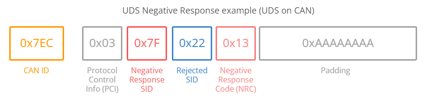
However, in some cases an ECU may provide a negative response to an UDS request – for example if the service is not supported. A negative response is structured as in below CAN frame example:
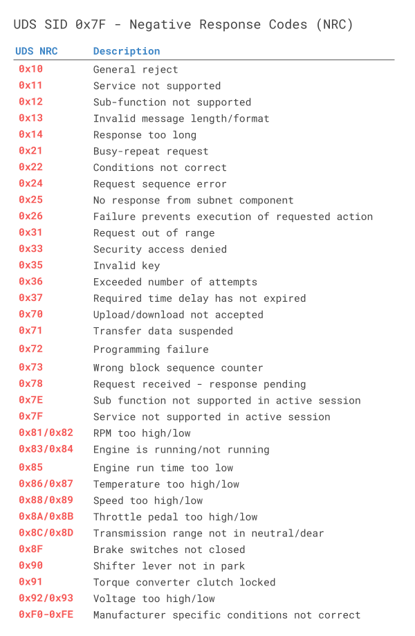
Below we briefly detail the negative response frame with focus on the NRC:
- The 1st byte is the PCI field
- The 2nd byte is the Negative Response Code SID, 0x7F
- The 3rd byte is the SID of the rejected request
- The 4th byte is the Negative Response Code (NRC)
In the negative UDS response, the NRC provides information regarding the cause of the rejection as per the table below.
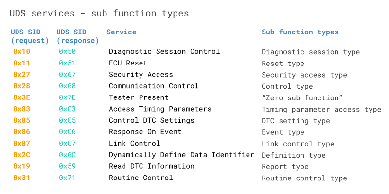
Functions of Diagnostic Services
Besides specifying services’ primitives and protocols that describe the client-server interaction, UDS also defines within its framework a number of functional units that comprise several services each, identified with a hexadecimal code. These units are intended for the different individual purposes that support the overall diagnostic function/task. The UDS protocol having different services for the different types of work tasks to do on the server. These are having 6- types as: 1. Diagnostic and communication management. 2. Data Transmission. 3. Stored Data Transmission. 4. Input/Output Control. 5. Remote activation of routine. 6. Upload/Download.
Diagnostic and communication management:
There are 10 services are available in this module to control the diagnostic and the communication-related in the ECU.
1. Diagnostic Session Control (0x10)
2. ECU Reset (0x11)
3. Security Access (0x27)
4. Communication Control (0x28)
5. Tester Present (0x3E)
6. Access Timing Parameter (0x83)
7. Secure Data Transmission (0x84)
8. Control DTC setting (0x85)
9. Response To Event (0x86)
10. Link Control (0x87)
| Function group | Request SID | Response SID | Service | Description |
|---|---|---|---|---|
| Diagnostic and Communications Management | $10 | $50 | Diagnostic Session Control | UDS uses different operating sessions, which can be changed using the “Diagnostic Session Control”. Depending on which session is active, different services are available. On start, the control unit is by default in the “Default Session”. Other sessions are defined, but are not required to be implemented depending on the type of device:”Programming Session” used to upload software.”Extended Diagnostic Session” used to unlock additional diagnostic functions, such as the adjustment of sensors.”Safety system diagnostic session” used to test all safety-critical diagnostic functions, such as airbag tests.In addition, there are reserved session identifiers that can be defined for vehicle manufacturers and vehicle suppliers specific use. |
| $11 | $51 | ECU Reset | The service “ECU reset” is used to restart the control unit (ECU). Depending on the control unit hardware and implementation, different forms of reset can be used:”Hard Reset” simulates a shutdown of the power supply.”key off on Reset” simulates the drain and turn on the ignition with the key.”Soft Reset” allows initialization of certain program units and their storage structures.Again, there are reserved values that can be defined for vehicle manufacturers and vehicle suppliers specific use. | |
| $27 | $67 | Security Access | Security check is available to enable the most security-critical services. For this purpose a “Seed” is generated and sent to the client by the control unit. From this “Seed” the client has to compute a “Key” and send it back to the control unit to unlock the security-critical services. | |
| $28 | $68 | Communication Control | With this service, both the sending and receiving of messages can be turned off in the control unit. | |
| $3E | $7E | Tester Present | If no communication is exchanged with the client for a long time, the control unit automatically exits the current session and returns to the “Default Session” back, and might go to sleep mode. Therefore, there is an extra service which purpose is to signal to the device that the client is still present. | |
| $83 | $C3 | Access Timing Parameters | In the communication between the controllers and the client certain times must be observed. If these are exceeded, without a message being sent, it must be assumed that the connection was interrupted. These times can be called up and changed. | |
| $84 | $C4 | Secured Data Transmission | ||
| $85 | $C5 | Control DTC Settings | Enable or disable the detection of any or all errors. This is important when diagnostic work is performed in the car, which can cause an anomalous behavior of individual devices. | |
| $86 | $C6 | Response On Event | ||
| $87 | $C7 | Link Control | The Service Link Control is used to set the baud rate of the diagnostic access. It is usually implemented only at the central gateway. | |
| Data Transmission | $22 | $62 | Read Data By Identifier | With this service it is possible to retrieve one or more values of a control unit. This can be information of all kinds and of different lengths such as Partnumber or the software version. Dynamic values such as the current state of the sensor can be queried. Each value is associated to a Data Identifier (DID) between 0 and 65535. Normal CAN signals are meant for information that some ECU uses in its functionality. DID data is sent on request only, and is for information that no ECU uses, but a service tool or a software tester can benefit from. |
| $23 | $63 | Read Memory By Address | Read data from the physical memory at the provided address. This function can be used by a testing tool, in order to read the internal behaviour of the software. | |
| $24 | $64 | Read Scaling Data By Identifier | ||
| $2A | $6A | Read Data By Identifier Periodic | With this service values are sent periodically by a control unit. The values to be sent must be defined to only using the “Dynamically Define Data Identifier”. | |
| $2C | $6C | Dynamically Define Data Identifier | This service offers the possibility of a fix for a device specified Data Identifier (DID) pool to configure another Data Identifier. This is usually a combination of parts of different DIDs or simply a concatenation of complete DIDs.The requested data may be configured or grouped in the following manner:Source DID, position, length (in bytes), Sub-Function Byte: defineByIdentifierMemory address length (in bytes), Sub-Function Byte: defineByMemoryAddressCombinations of the two above methods through multiple requests. | |
| $2E | $6E | Write Data By Identifier | With the same Data Identifier (DID), values can also be changed. In addition to the identifier, the new value is sent along. | |
| $3D | $7D | Write Memory By Address | ||
| Stored Data Transmission | $14 | $54 | Clear Diagnostic Information | Delete all stored DTC |
| $19 | $59 | Read DTC Information | control unit fault is stored with its own code in the error memory and can be read at any time. In addition to the error, additional information will be stored, which can also be read. | |
| Input / Output Control | $2F | $6F | Input Output Control By Identifier | This service allows an external system intervention on internal / external signals via the diagnostic interface.By specifying a so-called option bytes additional conditions for a request can be specified, the following values are specified:ReturnControlToECU: The device must get back controls of the mentioned signals.ResetToDefault: The tester prompts to reset signals to the system wide default value.Freeze Current State: The device shall freeze the current signal value.ShortTermAdjustment: The device shall use the provided value for the signal |
| Remote Activation of Routine | $31 | $71 | Routine Control | The Control service routine services of all kinds can be performed. There are three different message types:With the start-message, a service can be initiated. It can be defined to confirm the beginning of the execution or to notify when the service is completed.With the Stop message, a running service can be interrupted at any time.The third option is a message to query the results of the service.The start and stop message parameters can be specified. This makes it possible to implement every possible project-specific service. |
| Upload / Download | $34 | $74 | Request Download | Downloading new software or other data into the control unit is introduced using the “Request Download”. Here, the location and size of the data is specified. In turn, the controller specifies how large the data packets can be. |
| $35 | $75 | Request Upload | The service “request upload” is almost identical to the service “Request Download”. With this service, the software from the control unit is transferred to the tester. The location and size must be specified. Again, the size of the data blocks are specified by the tester. | |
| $36 | $76 | Transfer Data | For the actual transmission of data, the service “Transfer Data” is used. This service is used for both uploading and downloading data. The transfer direction is notified in advance by the service “Request Download” or “Upload Request”. This service should try to send packets at maximum length, as specified in previous services. If the data set is larger than the maximum, the “Transfer Data” service must be used several times in succession until all data has arrived. | |
| $37 | $77 | Request Transfer Exit | A data transmission can be ‘completed’ when using the “Transfer Exit” service. This service is used for comparison between the control unit and the tester. When it is running, a control unit can answer negatively on this request to stop a data transfer request. This will be used when the amount of data (set in “Request Download” or “Upload Request”) has not been transferred. | |
| $38 | $78 | Request File Transfer | This service is used to initiate a file download from the client to the server or upload from the server to the client. Additionally information about the file system are available by this service. | |
| $7F | Negative Response | This response is given when a service request could not be performed, for example having a not supported Data Identifier. A Negative Response Code will be included. |
UDS vs CAN bus: Standards & OSI model
To better understand UDS, we will look at how it relates to CAN bus and the OSI model.
Overview of UDS standards & concepts

The ISO 14229-1 standard describes the application layer requirements for UDS (independent of what lower layer protocol is used). In particular, it outlines the following:
- Client-server communication flows (requests, responses, …)
- UDS services (as per the overview described previously)
- Positive responses and negative response codes (NRCs)
- Various definitions (e.g. DTCs, parameter data identifiers aka DIDs, …)

The purpose of 14229-3 is to enable the implementation of Unified Diagnostic Services (UDS) on Controller Area Networks (CAN) – also known as UDSonCAN. This standard describes the application layer requirements for UDSonCAN.
This standard does not describe any implementation requirements for the in-vehicle CAN bus architecture. Instead, it focuses on some additional requirements/restrictions for UDS that are specific to UDSonCAN
Specifically, 14229-3 outlines which UDS services have CAN specific requirements. The affected UDS services are ResponseOnEvent and ReadDataByPeriodicIdentifier, for which the CAN specific requirements are detailed in 14229-3. All other UDS services are implemented as per ISO 14229-1 and ISO 14229-2.
ISO 14229-3 also describes a set of mappings between ISO 14229-2 and ISO 15765-2 (ISO-TP) and describes requirements related to 11-bit and 29-bit CAN IDs when these are used for UDS and legislated OBD as per ISO 15765-4.

This describes the session layer in the UDS OSI model. Specifically, it outlines service request/confirmation/indication primitives. These provide an interface for the implementation of UDS (ISO 14229-1) with any of the communication protocols (e.g. CAN).

For UDS on CAN, ISO 15765-2 describes how to communicate diagnostic requests and responses. In particular, the standard describes how to structure CAN frames to enable communication of multi-frame payloads. As this is a vital part of understanding UDS on CAN, we go into more depth in the next section.

When UDS is based on CAN bus, the physical and data link layers are described in ISO 11898-1 and ISO 11898-2. When UDS is based on CAN, it can be compared to a higher layer protocol like J1939, OBD2, CANopen, NMEA 2000 etc. However, in contrast to these protocols, UDS could alternatively be based on other communication protocols like FlexRay, Ethernet, LIN etc.
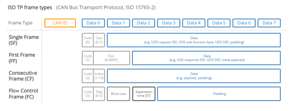
CAN ISO-TP – Transport Protocol (ISO 15765-2)
When implementing diagnostics on CAN, one challenge is the size of the CAN frame payload: For Classical CAN frames, this is limited to 8 bytes and for CAN FD the payload is limited to 64 bytes. Vehicle diagnostics often involves communication of far larger payloads.
ISO 15765-2 was established to solve the challenge of large payloads for CAN based vehicle diagnostics.
The standard specifies a transport protocol and network layer services for use in CAN based vehicle networks.
The ISO-TP standard outlines how to communicate CAN data payloads up to 4095 bytes through segmentation, flow control and reassembly. ISO-TP defines specific CAN frames for enabling this communication as shown below:
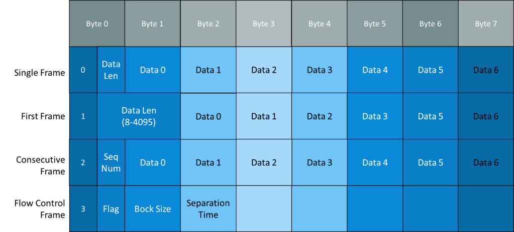
ISO-TP: Single-frame communication
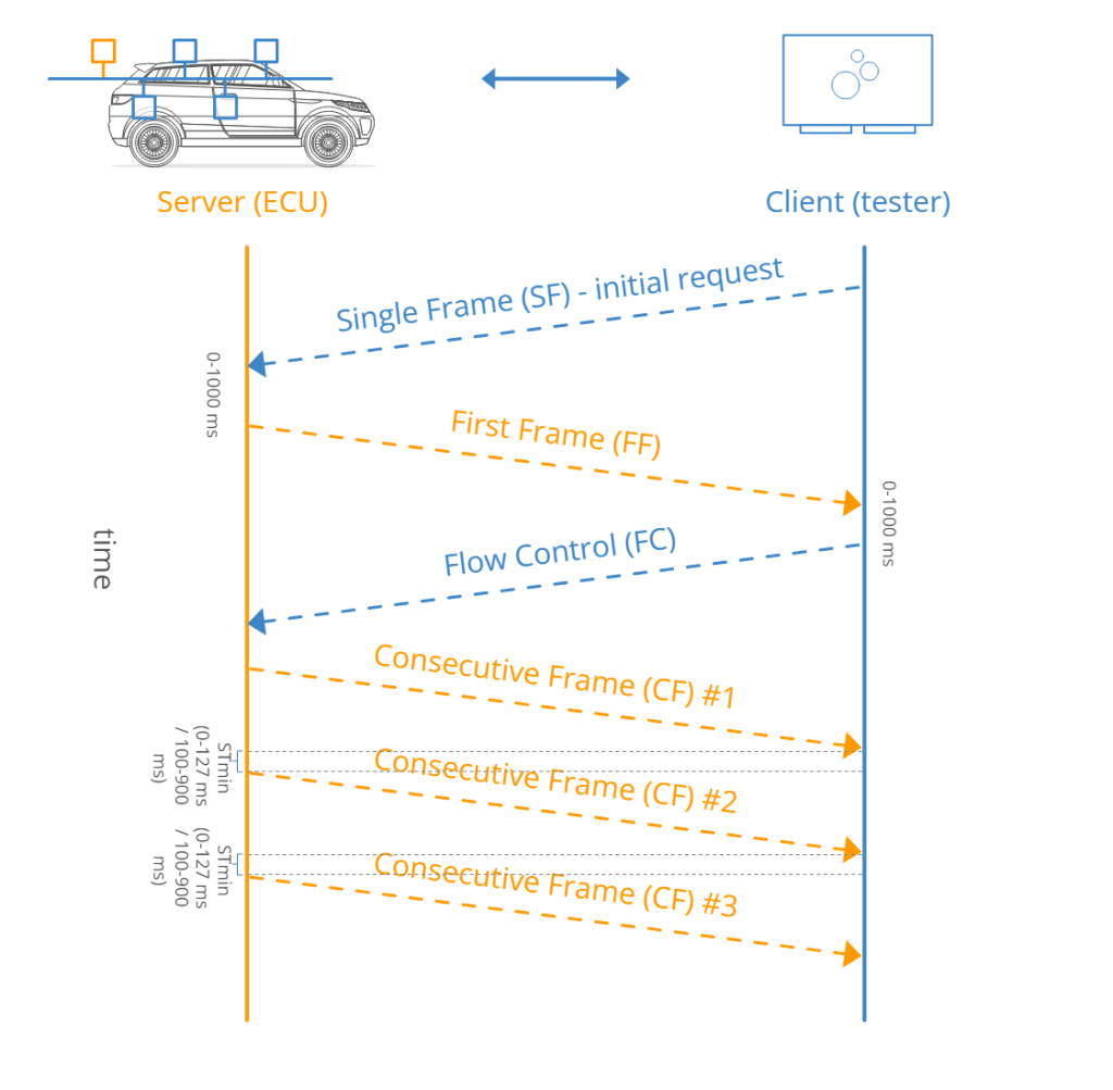
In vehicle diagnostics, communication is initiated by a tester tool sending a request. This request frame is a Single Frame (SF).
In the simplest case, a tester tool sends a Single Frame to request data from an ECU. If the response can be contained in a 7-byte payload, the ECU provides a Single Frame response.
ISO-TP: Multi-frame communication
When the payload exceeds 7 bytes, it needs to be split across multiple CAN frames.
As before, a tester starts by sending a Single Frame (SF) request to an ECU (sender). However, in this case the response exceeds 7 bytes.
Because of this, the ECU sends a First Frame (FF) that contains information on the total packet length (8 to 4095 bytes) as well as the initial chunk of data.
When the tester receives the FF, it will send a Flow Control (FC) frame, which tells the ECU how the rest of the data transfer should be transmitted.
Following this, the ECU will send Consecutive Frames (CF) that contain the remaining data payload.
Security Access Service Identifier (0x27): UDS Protocol
To prevent the ECU is modified by unauthorized persons most UDS services are locked. To get access to services that are used to modify the ECU the user first has to grant access through the Security Access Service Identifier (0x27). Only after the security access service has been passed, services like Request Download and Transfer Data can be used. The security concept used is called “Seed and Key”. Security Access Service flow:
- The client sends a request for a “seed” to the server that it wants to unlock.
- The server replies by sending the “seed” back to the client.
- The client then generates a “key” based on the “seed” and sends the key to the server.
- If the client generated the “key” with the correct algorithm the server will respond that the “key” was valid and that it will unlock itself.
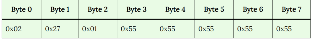
Security Access Seed Request Frame
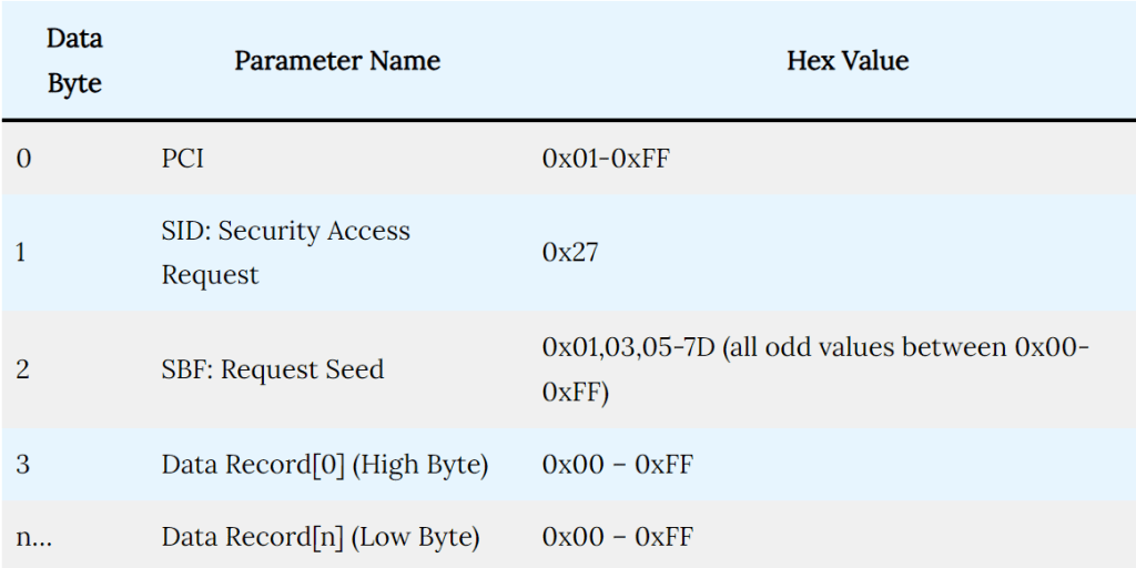
The above table defines what data format should be maintained to use the Security Access service in UDS Protocol for requesting a seed. Let me explain to you one example of how to request a seed:
Security Access Seed Response Frame
The response message has a response SID and if it is a positive response the parameter is an echo of the request message parameter. If it is a negative response the parameter is one of eight negative response codes.
