What is BUS Systems And Why Required?
- In past electronic devices in vehicles are connected via point to point wiring system.
- More Electronic in vehicle which resulted in bulky wire harnesses that were expensive and heavy too and if new nodes need to be introduced, it will be very difficult and complex.
- In electronic systems signals are sent from one chip to another using wires (let’s forget about wireless things for a second). The simplest way of doing so is to use one wire per bit of information you like to transmit. One bit of information is simply an answer to a yes/no question like “Are the headlights on?” If the headlights are on, there is a voltage on that wire, say 5 volts. If they are off there are 0 volts on the wire.
- Now that’s fine for one bit of information. But more data requires more wires. Unfortunately: More wires means more complexity. A modern car is just a computer with wires on it, so there are a lot of wires (several km or miles) in it. More wires result in more weight and more costs and car manufacturers don’t like that. So we need a way to reduce the amount of wires.
The usual way of doing so is to use a bus system.
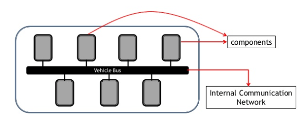
- Think of a bus as a way to transmit more information using fewer wires.
- So Vehicle Bus is an internal communication network that interconnects components inside a vehicle
What are the difference between an OBD-II protocol and a CAN setup?
OBD-II is a higher-level protocol used for diagnostic purposes. OBD-II can use one of (many) different bus systems to transfer diagnostic data from and to your car. Think of OBD-II as a language (English) that you speak and of CAN as the communication device (telephone) you use to talk to someone (about your car and its state of health.
What is CAN?
- CAN (Controller Area Network) is a serial bus system, which was originally developed for automotive applications in the early 1980’s.
- The CAN bus was developed by BOSCH (1) as a multi-master, message broadcast system that specifies a maximum signaling rate of 1 megabit per second (bps).
- CAN is a two-wire, half duplex, high-speed network system, that is far superior to conventional serial technologies such as RS232 in regards to functionality and reliability and yet CAN implementations are more cost effective
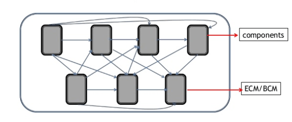
- The CAN bus is a broadcast type of bus. This means that all nodes can “hear” all transmissions. There is no way to send a message to just a specific node; all nodes will invariably pick up all traffic.
- Unlike a traditional network such as USB or Ethernet, CAN does not send large blocks of data point-to-point from node A to node B under the supervision of a central bus master.
CAN Bus Explained with an Analogy
Imagine that your car is like a human body:
The Controller Area Network (CAN bus) is the nervous system, enabling communication between all parts of the body.
Similarly, ‘nodes’ are like muscles connected via the CAN bus, which acts as a central networking system. In turn, electronic control units (ECU) are like arms and legs.
- Each of the devices on the network has a CAN controller chip and is therefore intelligent. All transmitted messages are seen by all devices on the network. Each device can decide if the message is relevant or if it can be filtered.
Specifications:
· Provides better ease of use than any other serial bus system
· Operates at data rates of up to 1 Megabit per second
· Has excellent error detection and fault confinement capabilities
• Up to 1 Mbit/s at cable length 40 m
• 0 – 8 bytes of data/frame
• Event triggered, messages are sent when there is something to send
• No specified connectors but often 9 pin DSUB
• CDMA/CR – Carrier Sence Multiple Access/Collision Resolution
- Two-wire bus network
- Multi-master
- Follows the OSI layer model for networks
Multi Broadcast bus
Theoretical maximum of 2,032 nodes per bus
– Practical limit is approximately 100 nodes due to transceiver
– Most buses use 3–10 nodes
CAN Standard
- CAN is an International Standardization Organization (ISO) defined serial communications bus originally developed for the automotive industry to replace the complex wiring harness with a two-wire bus.
- The CAN communications protocol, ISO-11898: , describes how information is passed between devices on a network and conforms to the Open Systems Interconnection (OSI) model that is defined in terms of layers
- The data link layer protocol defined by ISO 11898-1 and the physical layer defined by ISO 11898-2.
- The ISO 11898 architecture defines the lowest two layers of the seven layer OSI/ISO model as the data-link layer and physical layer
CAN Working Principle
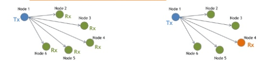
CAN is multi master message model Any node can transmit or receive any message
Data transmitted From any Node on CAN bus Nodes does not contain Addresses of either the transmitting Node or any intended receiving Node instead it contains Message Which will be labelled By an Identifier
All Other Nodes Receive the message & Perform an acceptance test on the identifier to determine if the message & thus its content is relevant to that Particular Node
If Message is relevant it will be Processed Otherwise It is Ignored
What is meant when referring to a physical layer, or an application layer?
The International Organization for Standardization (ISO) developed the Open System Interconnect (OSI) model in 1984 as a model of computer communication architecture. There are seven layers to the OSI model: Physical, Data Link, Network, Transport, Session, Presentation, and Application. The intent is that protocols be developed to perform the functions of each layer as needed.
The OSI layer model
Layer1 –
- The physical layer transmits bit from one device to another and regulates the transmission of bit streams. It defines the specific voltage and the type of cable to be used for transmission protocols. It provides the hardware means of sending and receiving data on a carrier defining cables, cards and physical aspects.
- Layer 2 – Data link layer Converts data frames from the bits on the wire to packages that the network layer can handle It packages raw data into frames transferred from physical layer. This layer is responsible for transferring frames from one device to another without errors. After sending the frame it waits for the acknowledgement from receiving device. Data link layer has two sub layers:
- MAC (Medium Access Control) layer: It performs frame coding, error detection, signaling, serialization and de-serialization.
- LLC (Logical Link Control) layer: The LLC sub layer provides multiplexing mechanisms that make it possible for several network protocols (IP, Decnet and Appletalk) to coexist within a multipoint network and to be transported over the same network medium. It performs the function of multiplexing protocols transmitted by MAC layer while transmitting and decoding when receiving and providing node-to-node flow and error control.
- Layer 3 – Network layer Handles data paths. Converts logical addresses to physical addresses It provides end to end logical addressing system so that a packet of data can be routed across several layers and establishes, connects and terminates network connections.
- Layer 4 –The transport layer ensures that messages are delivered error-free, in sequence, and without loss or duplication. It relieves the higher layer from any concern with the transfer of data between them and their peers.
- Layer5– It allows to establishing, communicating and terminating sessions between processes running on two different devices performing security, name recognition and logging.
- Layer 6 – Presentation layer Converts between the data format of the application and the data format of the network The most important function of this layer is defining data formats such as ASCII text, EBCDIC text BINARY, BCD and JPEG. It acts as a translator for data into a format used by the application layer at the receiving end of the station.
- Layer 7 –Application layer It serves as a window for users and application processes to access network services. The common functions of the layers are resource sharing, remote file access, network management, electronic messages and so on.
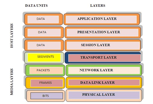
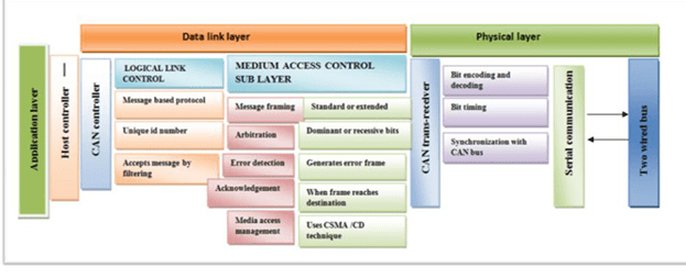
CAN protocol uses lower two layers of OSI i.e. physical layer and data link layer. The remaining five layers that are communication layers are left out by BOSCH CAN specification for system designers to optimize and adapt according to their needs.
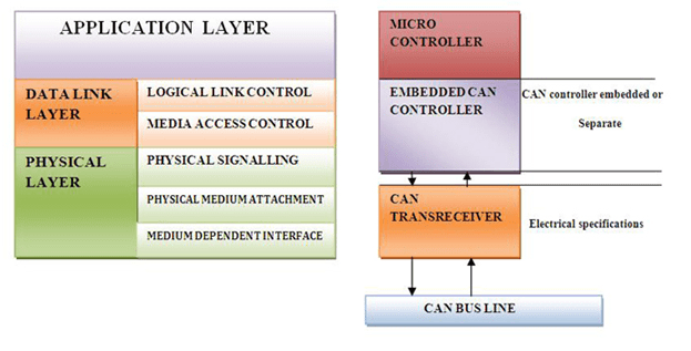
The concept of the CAN protocol can be understood using the figure above. Every node has a Host controller also known as micro-controller which is a small and low-cost computer .Host controller implements application layer of OSI model. Micro-controller gathers information from other electronic control units like braking, steering, power windows etc. to communicate with other nodes and transfers it to CAN controller. CAN controller incorporate logical link control and MAC medium access control of data link layer. LLC allows filtering of messages by using unique ID on each message then MAC sub layer frames the message. Once, framing is done it is followed by arbitration, error detection and acknowledgement that all comes under MAC sub layer of data link. The frame is transferred to CAN trans-receiver, for encoding and decoding. Finally CAN trans-receiver synchronizes with the CAN bus to send the message to anther node.
Advantages of CAN Bus Communication
- Low-Cost, Lightweight Network
CAN provides an inexpensive, durable network that helps multiple CAN devices communicate with one another. An advantage to this is that electronic control units (ECUs) can have a single CAN interface rather than analog and digital inputs to every device in the system. This decreases overall cost and weight in automobiles - Centralized: The CAN bus system allows for central error diagnosis and configuration across all ECUs
- Robust: The system is robust towards electric disturbances and electromagnetic interference, making it ideal for e.g. vehicles
- Flexible: Each CAN-connected ECU can receive all transmitted messages. It decides relevance and acts accordingly – this allows easy modification and inclusion of additional nodes (e.g. CAN bus data loggers)
- Broadcast Communication
Each of the devices on the network has a CAN controller chip and is therefore intelligent. All devices on the network see all transmitted messages. Each device can decide if a message is relevant or if it should be filtered. This structure allows modifications to CAN networks with minimal impact. Additional non-transmitting nodes can be added without modification to the network. - Priority
Every message has a priority, so if two nodes try to send messages simultaneously, the one with the higher priority gets transmitted and the one with the lower priority gets postponed. This arbitration is non-destructive and results in non-interrupted transmission of the highest priority message. This also allows networks to meet deterministic timing constraints. - Error Capabilities
The CAN specification includes a Cyclic Redundancy Code (CRC) to perform error checking on each frame’s contents. Frames with errors are disregarded by all nodes, and an error frame can be transmitted to signal the error to the network. Global and local errors are differentiated by the controller, and if too many errors are detected, individual nodes can stop transmitting errors or disconnect itself from the network completely.
The main applications for CAN are in the fields of
- Passenger Cars
- Trucks and Buses
- Off-Road Vehicles
- Passenger and Cargo Trains
- Maritime Electronics
- Aircraft and Aerospace Electronics
- Factory Automation
- Industrial Machine Control
- Building Automation
- Lifts and Escalators
- Medical Equipment and Devices
