Types of CAN Communication Protocol
High-Speed/FD CAN:
High-speed CAN is by far the most common physical layer. High-speed CAN networks are implemented with two wires and allow communication at transfer rates up to 1 Mbit/s. Other names for high-speed CAN include CAN C and ISO 11898-2. Typical high-speed CAN devices include antilock brake systems, engine control modules, and emissions systems. CAN with Flexible Data-Rate (CAN FD) is the next generation of high-speed CAN communication with evolving standards for higher data rates.
Low-Speed/Fault-Tolerant CAN Hardware:
Low-speed/fault-tolerant CAN networks are also implemented with two wires, can communicate with devices at rates up to 125 kbit/s, and offer transceivers with fault-tolerant capabilities. Other names for low-speed/fault-tolerant CAN include CAN B and ISO 11898-3. Typical low-speed/fault-tolerant devices in an automobile include comfort devices. Wires that have to pass through the door of a vehicle are low-speed/fault-tolerant in light of the stress that is inherent to opening and closing a door
Single-Wire CAN Hardware:
Single-wire CAN interfaces can communicate with devices at rates up to 33.3 kbit/s (88.3 kbit/s in high-speed mode). Other names for single-wire CAN include SAE-J2411, CAN A, and GMLAN. Typical single-wire devices within an automobile do not require high performance. Common applications include comfort devices such as seat and mirror adjusters.
CAN Terminology:
- Bit Rate the number of bits per second that can be transmitted along a digital network. Bit rate is also known as bitrate or data rate.
In networking and digital telecommunications, bit rate refers to the per-second measurement of data that passes through a communications network. In this context, bit rate is synonymous with data transfer rate (DTR).
For multimedia encoding, bit rate refers to the number of bits used per unit of playback time, such as video or audio after compression (encoding). Multimedia size and output quality often depend on the bit rate used during encoding.
Therefore, in both cases:
BR = D ÷ T
Where:
BR = Bit Rate
D = Amount of Data
T = Time (usually seconds)
BIT Time
- The duration of an individual one (1) or zero (0) bit in a digital transmission. The transmitter ejects bits at a given rate (x bits per second), with each bit occupying the circuit for a given amount of time, which is the inverse of the bit rate (1/x seconds per bit). The receiver must monitor the circuit at precisely the same rate and at the same instants in time in order to distinguish the individual bits.
- Propagation speed is the amount of time it takes for one particular signal to get from one point to another.
- Transmission Rate is the total amount of data that can be sent from one place to another in a given period of time.
- The propagation delay, is the time it takes a bit to propagate from one router to the next.
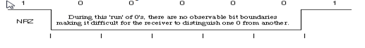
NRZ bit coding
NRZ bit coding (NRZ: Non Return to Zero) was chosen for CAN. This means that the binary signals to be transmitted are mapped directly: a logic “1” to a high level, a logic “0” to a low level. Characteristic of NRZ coding is that consecutive bits of the same polarity exhibit no level changes.
This is how NRZ coding enables very high data rates yet keeps emissions within limits. However, NRZ coding is not self-clocking; that is, it does not have any synchronization properties. If no level change occurs over a longer period of time, the receiver loses synchronization. That is why the use of NRZ coding requires an explicit synchronization mechanism, which however reduces transmission efficiency.
With CAN what is known as the bit stuffing method is used as the synchronization mechanism: after five homogeneous bits the sender inserts a complementary bit in the bit stream (Manchester coding, for example, does without such a mechanism, since it is self-clocking).
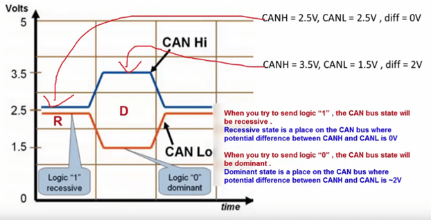
How do CAN bus modules communicate?
CAN bus uses two dedicated wires for communication. The wires are called CAN high and CAN low. When the CAN bus is in idle mode, both lines carry 2.5V. When data bits are being transmitted, the CAN high line goes to 3.75V and the CAN low drops to 1.25V, thereby generating a 2.5V differential between the lines. Since communication relies on a voltage differential between the two bus lines, the CAN bus is NOT sensitive to inductive spikes, electrical fields or other noise. This makes CAN bus a reliable choice for networked communications on mobile equipment.
CAN power can be supplied through CAN bus. Or a power supply for the CAN bus modules can be arranged separately. The power supply wiring can be either totally separate from the CAN bus lines (using suitable gauge wiring for each module) resulting in two 2-wire cables being utilized for the network, or it can be integrated into the same cable as the CAN bus lines resulting in a single 4-wire cable. CAN bus cabling is available from multiple vendors.
What is CAN protocol and how is it implemented?**
CAN protocol can be defined as the set of rules for transmitting and receiving messages in a network of electronic devices. It means that it defines how data is transferred from one device to another in a network. It was designed specifically looking into the needs of the automobile industry. However CAN’s robust architecture and advantages has forced many industries like Railway, Aircraft’s, medical etc to adopt CAN protocol in their systems.
Every electronic device (also known as the node) which needs to communicate using the CAN protocol is connected with each other via a common serial bus to transmit and receive messages.
For data exchange to happen among the nodes they must have the necessary hardware and the software embedded inside them.
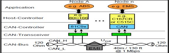
in addition to the host controller every node has a CAN controller and CAN transceiver. CAN controller convert the messages of the nodes in accordance with the CAN protocols to be transmitted via CAN transceiver over the serial bus and vice versa. CAN controller is a chip which can either be added separately or embedded inside the host controller of the node.
CAN does not follow the master-slave architecture which means every nodes has the access to read and write data on the CAN bus. When the node is ready to send data, it checks availability of the bus and writes a CAN frame onto the network. A frame is defined structure, carrying meaningful sequence of bit or bytes of data within the network. CAN transmitted frame does have address neither of transmitting node or the receiving node. CAN is a message based protocol. A message can be defined as a packet of data which carries information. A CAN message is made up of 10 bytes of data. The data is organized in a specific structure called frame and the information carried in every byte is defined in the CAN protocol. Protocols are generally of two types: address based and message based. In an address based protocol the data packets contain the address of the destination device for which the message is intended. In a message based protocol every message is identified by a predefined unique ID rather than the destination addresses. All nodes on CAN receive the CAN frame and depending on ID on the node CAN decides whether to accept it or not. If multiple nodes send the message at the same time than the node with highest priority (lowest arbitration ID) gets the bus access. Lower priority nodes wait till the bus is available
Principle of Bus Arbitration in CAN networks
- The CAN communication protocol is a carrier-sense, multiple-access protocol with collision detection and arbitration on message priority (CSMA/CD+AMP).
- CSMA means that each node on a bus must wait for a prescribed period of inactivity before attempting to send a message.
- CD+AMP means that collisions are resolved through a bit-wise arbitration, based on a preprogrammed priority of each message in the identifier field of a message.
The message arbitration (the process in which two or more CAN controllers agree on who is to use the bus) is of great importance for the really available bandwidth for data transmission.
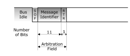
Any CAN controller may start a transmission when it has detected an idle bus. This may result in two or more controllers starting a message (almost) at the same time. The conflict is resolved in the following way. The transmitting nodes monitor the bus while they are sending. If a node detects a dominant level when it is sending a recessive level itself, it will immediately quit the arbitration process and become a receiver instead. The arbitration is performed over the whole Arbitration Field. The arbitration field follows right after the SOF (Start of Frame) bit and it contains of the message ID and the RTR (Remote Transmission Request) bit.
And when that field has been sent, exactly one transmitter is left on the bus. This node continues the transmission as if nothing had happened. The other potential transmitters will try to re transmit their messages when the bus becomes available next time. No time is lost in the arbitration process.
Main Rules of Bus Arbitration
The main rules of bus arbitration are:
- Bit wise arbitration across the Arbitration Field
Zero Bit = Dominant Bus Level, One Bit = Recessive Bus Level, dominant bit overrides recessive bit
The CAN bus level will be dominant in case any number of nodes in the network output a dominant level. The CAN bus level will only be recessive when all nodes in the network output a recessive level.
An equivalent from some electronics basics will explain the relationship between node output and the resulting bus level as shown in picture
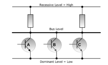
This example uses three nodes in a CAN network, in this case represented by three transistors in open-collector configuration (“Wired And”). The bus level will be at low level (dominant) in case any number of transistors in the network output a dominant level. The bus level will only be at high level (recessive) when all transistors in the network output a recessive level.
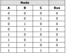
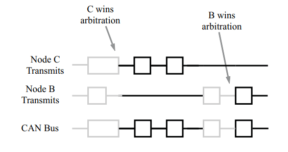
Figure displays the CAN arbitration process that is handled automatically by a CAN controller. Because each node continuously monitors its own transmissions, as node B’s recessive bit is overwritten by node C’s higher priority dominant bit, B detects that the bus state does not match the bit that it transmitted. Therefore, node B halts transmission while node C continues on with its message. Another attempt to transmit the message is made by node B once the bus is released by node C. This functionality is part of the ISO 11898 physical signaling layer, which means that it is contained entirely within the CAN controller and is completely transparent to a CAN user
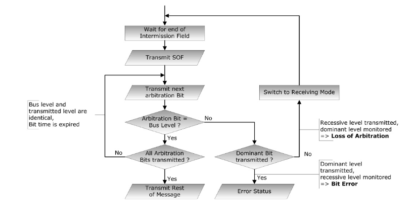
- The CAN node (CAN controller) waits for the end of the intermission field .
- As soon as the bus is being detected as idle, the CAN node signals an SOF (Start of Frame) by putting a dominant (low) level onto the bus. Every other node in the network, that did not request bus access, will immediately switch to a receiving mode.
- The CAN controller sends the first/next message ID bit (Message IDs can be 11 or 29 bit long, the most significant bit – MSB will be sent first).
- The CAN controller compares its output signal with the actual bus level (at the end of each bit cycle).
- The node will lose the arbitration, in case it did send a recessive level (high) and detects a dominant (low) bus level. Consequently the node will switch into receiving mode.
- An error condition exists when the node detects a recessive level on the bus after it did output a dominant level. This is a clear violation of the CAN standard and the node will send an error frame to the bus.
- If the node has finished sending all arbitration bits (message ID plus RTR) without loosing the bus arbitration, it will transmit the rest of the message. At this time all other CAN nodes in the network will have switched to receiving mode.
An important condition for this bit-wise arbitration to succeed is that no two nodes may transmit the same Arbitration Field. There is one exception to this rule: if the message contains no data, then any node may transmit that message.
Since the bus is wired-and and a Dominant bit is logically 0, it follows that the message with the numerically lowest Arbitration Field will win the arbitration
Q: What happens if a node is alone on the bus and tries to transmit?
The node will, of course, win the arbitration and happily proceeds with the message transmission. But when the time comes for acknowledging… no node will send a dominant bit during the ACK slot, so the transmitter will sense an ACK error, send an error flag, increase its transmit error counter by 8 and start a re transmission. This will happen 16 times; then the transmitter will go error passive. By a special rule in the error confinement algorithm, the transmit error counter is not further increased if the node is error passive and the error is an ACK error. So the node will continue to transmit forever, at least until someone acknowledges the message.
The standard form of arbitration in a CAN network is Carrier Sense Multiple Access/Bitwise Arbitration (CSMA/BA). If two or more nodes start transmitting at the same time, arbitration is based on the priority level of the message ID, and allows the message whose ID has the highest priority to be delivered immediately, without delay
Each node, when it starts to transmit its Message ID, will monitor the bus state and compare each bit received from the bus with the bit transmitted. If a dominant bit (0) is received when a recessive bit (1) has been transmitted, the node stops transmitting because another node has established priority.
- Each node transmits its 11-bit Message ID, starting with the highest-order bit (bit 10). Binary zero (0) is a dominant bit, and binary one (1) is a recessive bit
Because a dominant bit will overwrite a recessive bit on the bus, the state of the bus will always reflect the state of the message ID with the highest priority (i.e. the lowest number)
- As soon as a node sees a bit comparison that is un favorable to itself, it will cease to participate in the arbitration process and wait until the bus is free again before attempting to retransmit its message. The message with the highest priority will thus continue to be transmitted without delay, and unimpeded
- In the above illustration, Node 2 transmits bit 5 as a recessive bit (1), while the bus level read is dominant (0), so Node 2 will back off. Similarly, Node 1 will back off after transmitting bit 2 as a recessive bit, whereas the bus level remains dominant. Node 3 is then free to complete transmission of its message.
The Layout of a Bit**— (To be Updated)
Each bit on the CAN bus is, for timing purposes, divided into at least 4 quanta. The quanta are logically divided into four groups or segments –
- the Synchronization Segment
- the Propagation Segment
- the Phase Segment 1
- the Phase Segment 2
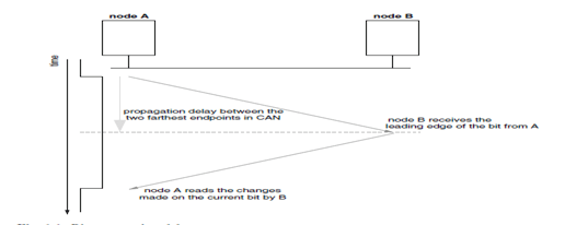
Why the bit (transmission) time must be at least large enough to accommodate the signal propagation from any sender to any receiver and back to the sender?
Bus arbitration, message acknowledgement and error signaling are based on the capability of the nodes to change the status of a transmitted bit from recessive to dominant. Since the bus is shared, all other nodes in the network are informed of the change in the bit status before the bit transmission ends. Therefore, the bit (transmission) time must be at least large enough to accommodate the signal propagation from any sender to any receiver and back to the sender.
The bit time needs to account for a propagation delay that includes the signal propagation delay on the bus as well as delays caused by the electronic circuitry of the transmitting and receiving nodes. In practice, this means that the signal propagation is determined by the two nodes within the system that are farthest apart from each other as the bit is broadcast-ed to all nodes in the system.
The leading bit edge from the transmitting node (node A) reaches node B after the signal propagates all the way from the two nodes. At this point, B can change its value from recessive to dominant, but the new value will not reach A until the transition from recessive to dominant propagates across the entire bus length from B back to A. Only then can node A safely determine whether the signal level it wrote on the bus is the actual stable level for the bus at the bit sampling time, or whether it has been replaced (in case it was recessive) by a dominant level superimposed by another node.
Why Bit stuffing needed
Nodes are requested to be synchronized on the bit edges so that every node agrees on the value of the bit currently transmitted on the bus. To achieve synchronization each node implements a protocol that keeps the receiver bit rate aligned with the actual rate of the transmitted bits. The synchronization protocol uses transition edges to re synchronize nodes. Hence, long sequences without bit transitions should be avoided to ensure limited drift among the node bit clocks. This is the reason why the protocol employs the so-called “bit stuffing” or “bit padding” technique, which forces a complemented bit in a transmission sequence after 5 bits of the same type. Stuffing bits are automatically inserted by the transmission node and removed at the receiving side before processing the frame contents.
Why Cable Length length needs to be limited?
While a station is competing for the bus, it also observes if its data is the same as the data on the bus. If different, the node assumes that a higher priority message is already on the bus and switches to receiving mode. In this way, the highest priority message is ensured to get the bus while lower priority messages are sent later. With this method, no time is wasted on collisions and valuable bandwidth is saved . However, this arbitration mechanism limits the bus length, because all stations have to observe each other within a period of one bit time. Because of the propagation delay on a bus and the delays of nodes, CAN segments have to be short, only 40m at 1 Mbps
How the Cable length can Be increased for Industrial Application?
The first is to decrease the data rate, hence the time for one bit is increased. The second solution is to use additional interconnection devices, such as bridges.
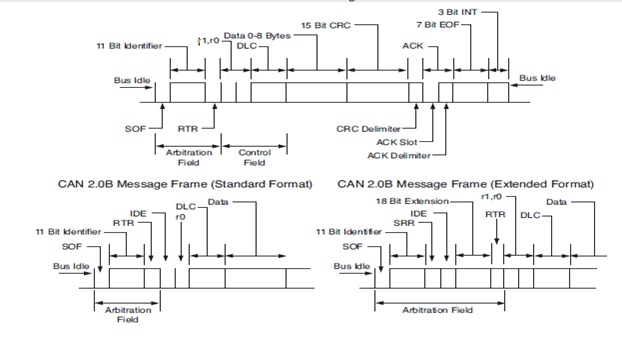
The Bit Fields of Standard CAN and Extended CAN
The ISO-11898:2003 Standard, with the standard 11-bit identifier, provides for signaling rates from 125 kbps to 1 Mbps. The standard was later amended with the “extended” 29-bit identifier. The standard 11-bit identifier field in provides for 211, or 2048 different message identifiers, whereas the extended 29bit identifier provides for 229, or 537 million identifiers
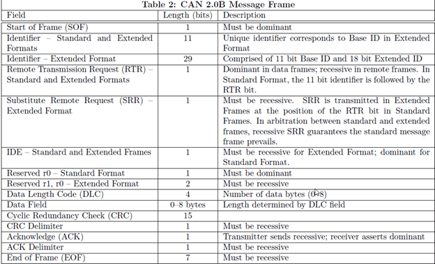
The difference between a CAN 2.0A and a CAN 2.0B message is that CAN 2.0B supports both 11 bit (standard) and 29 bit (extended) identifiers. Standard and extended frames may exist on the same bus, and even have numerically equivalent identifiers. In this case, the standard frame will have the higher priority.
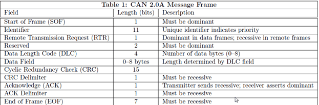
Standard CAN:
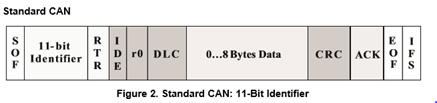
- SOF (1 Bit) The dominant Start of Frame (SOF) bit represents the start of a Data/Remote Frame and, in all consequence, also starts the arbitration sequence (the arbitration field follows right after the SOF bit). Thus, before attempting to access the bus, a CAN node must wait until the bus is idle. A sequence of 11 recessive bits detects an idle bus, i.e., the sequence of ACK Delimiter bit in the Acknowledgement Field (1 bit), the End of Frame Field (7 bits), and the Intermission Field (3 bits).The falling (leading) edge of the SOF bit (transition from recessive to dominant level), sent by the first node that attempts to access the bus, also serves as a mechanism to synchronize all CAN bus nodes.
Arbitration Field (12 or 32 Bits)
The arbitration field contains of two components:
- 11/29 Bit Message Identifier, first Bit is MSB. As will be explained later, the CAN message ID can be 11 or 29 bits long.
- RTR (Remote Transmission Request) indicates either the transmission of a Data Frame (RTR = 0) or a Remote-Request Frame (RTR = 1).
A low message ID number represents a high message priority.
A Data Frame has higher priority than a Remote Frame.
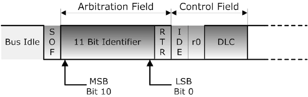
The total length of the arbitration field is 12 bits when an 11 bit message identifier is used (see picture below).
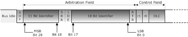
As shown in the picture, the total length of the arbitration field will be 32 bit with a 29 bit identifier (see also Chapter 4.6 – Extended CAN Protocol).
An 11 bit identifier (standard format) allows a total of 211 (= 2048) different messages. A 29 bit identifier (extended format) allows a total of 229 (= 536+ million) messages.
The IDE (Identifier Extension) bit belongs to:
– The Control Field of the standard format (11 bit message identifier)
– The Arbitration Field of the extended format (29 bit message identifier)
- RTR: The Remote Transmission Request indicates whether a node sends data or requests dedicated data from another node. This bit is used to differentiate a remote frame from a data frame. A logic 0 (dominant bit) indicates a data frame. A logic 1 (recessive bit) indicates a remote frame.
- IDE–A dominant single identifier extension (IDE) bit means that a standard CAN identifier with no extension is being transmitted This bit allows differentiation between standard and extended frames.
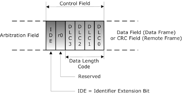
r0, were always sent as dominant (zero), which, according to standard CAN 2.0B, indicates an 11-bit identifier per default.
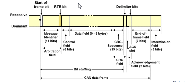
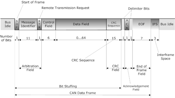
- DLC – Data length code – It indicates the number of bytes the data field contains The 4-bit data length code (DLC) contains the number of bytes of data being transmitted
- Data–Up to 64 bits of application data may be transmitted. Contains the actual data values, which need to be “scaled” or converted to be readable and ready for analysis.
- CRC – Cyclic Redundancy Check – The CRC field is used for error detection. It contains 15-bit cyclic redundancy check code and a recessive delimiter bit.
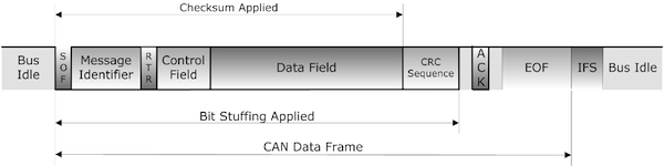
The 15 bit CRC Segment contains the frame check sequence spanning from SOF (Start of Frame), through the arbitration field, control field and data field. Stuffing Bits are not included.
- The CRC Delimiter Bit (always recessive, i.e., 1)
- ACK– The ACK slot indicates if the node has received the data correctly Every node receiving an accurate message overwrites this recessive bit in the original message with a dominate bit, indicating an error-free message has been sent. Should a receiving node detect an error and leave this bit recessive, it discards the message and the sending node repeats the message after re arbitration. In this way, each node acknowledges (ACK) the integrity of its data. ACK is 2 bits, one is the acknowledgment bit and the second is a delimiter any CAN controller that correctly receives the message sends an ACK bit at the end of the message. The transmitting node checks for the presence of the ACK bit on the bus and reattempts transmission if no acknowledge is detected
End-of-Frame Field (7 bits, recessive)
Each data or remote frame is terminated by a bit sequence of 7 recessive bits.
Each CAN message frame, regardless of the message ID length, will be terminated by a sequence of 11 recessive bits: The ACK Delimiter bit in the Acknowledgement Field (1 bit), the End of Frame Field (7 bits), and the Intermission Field (3 bits).
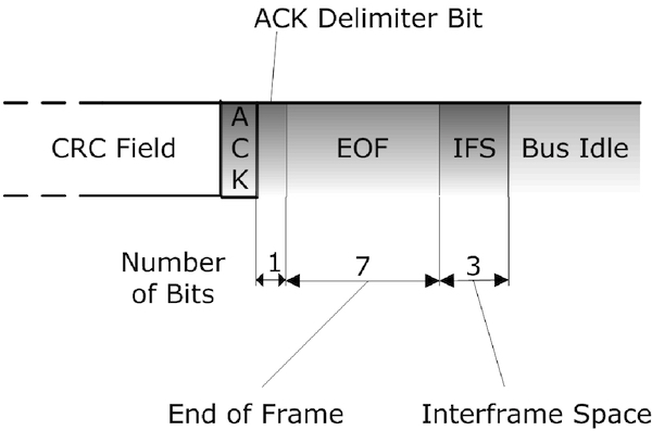
Interframe Space (3 bits, recessive)
The Interframe Space represents the minimum space between frames of any type (data, remote, error, overload) and the following data or remote frame. During the Interframe Space (intermission), no node can start transmitting a data or remote frame. Only the signaling of an overload condition is allowed (see Chapter 4.8 – Overload Frame). There is no Interframe space between error and overload frames. The Interframe Space can not necessarily be considered to be a part of a data or remote frame; however, in a well-functioning CAN network, it will always follow behind a data or remote frame. For more detailed information, see also Chapter 4.9 – Interframe Space.
What is a CRC delimiter in CAN frame format?
- The Delimiter Bits: other than providing the time for synchronization , the delimiter serves a specific purpose in Error Detection.
- A type of Error Detection called Form Check: Form check basically checks that the CAN frame sent/received is in a standard format , as depicted in the above picture the CAN frame format must be maintained throughout the communication.
- i.e. the receiver checks for the delimiter bits after properly receiving the identifier and data.
- The delimiter bits must come at a predefined place so that the form of the CAN frame is maintained.
- if the receiver does not find the delimiter bits at a proper place , it generates an Form Error Frame.
Cyclic redundancy check (CRC) in CAN frames
CAN data frames and remote frames contain a safeguard based on a CRC polynomial: The transmitter calculates a check sum from the transmitted bits and provides the result within the frame in the CRC field. The receivers use the same polynomial to calculate the check sum from the bits as seen on the bus-lines. The self-calculated check sum is compared with the received on. If it matches, the frame is regarded as correctly received and the receiving node transmits a dominant state in the ACK slot bit, overwriting the recessive state of the transmitter. In case of a mismatch, the receiving node sends an Error Frame after the ACK delimiter.
Is it possible to send both standard and extended CAN frames on same bus?
Yes, it is possible to transmit and receive both standard and extended CAN Frame on the same bus. The CAN controller can identify the extended CAN frame using recessive IDE bit.
In a CAN network, if the same ID number is shared between standard and extended messages if it comes to arbitration, which message will win the bus access?
In case of arbitration between Standard df and Exrended df standard df will always Have Priority
Of Both Message have same 11 Bit Identifier If you carefully study the frame structure the answer lies within, two images of standard CAN frame and Extended CAN frame, disregard the first two i.e. SOF and identifier, since they are identical in both frames.
In the case of a 29 bit extended frame, the RTR bit has been moved to the end of the message so it doesn’t play in the priority bitwise arbitration of the 29 bit IDs. That’s why the Standard frame RTR now defined as SRR is transmitted as recessive. It prevents a 29 bit RTR message from having a higher priority than a non RTR message.
To sum up SRR bit is recessive always so Standard CAN wins the arbitration but both messages can exist on the network.
How Acknowledgement Field Works
Unlike other serial communications, such as RS232, the acknowledgment field does not serve as a signal for the successful or unsuccessful reception of a message by a receiving node (consider that there may be numerous receiving nodes in a CAN network). The acknowledgment field serves as a confirmation of a successful CRC (checksum) check by the receiving nodes in the network.
During the ACK slot, the message transmitting node switches to receive mode by sending a recessive signal to the bus. At the same time, all other nodes in the network accomplish their individual CRC (checksum) check (according to the CAN standard, all nodes must determine the checksum in the same standardized way) and output a dominant signal to the bus when the check was successful.
The message transmitting node monitors the bus and expects a dominant level during the ACK slot. This will be the case when either one of the receiving CAN Bus nodes outputs a dominant level.
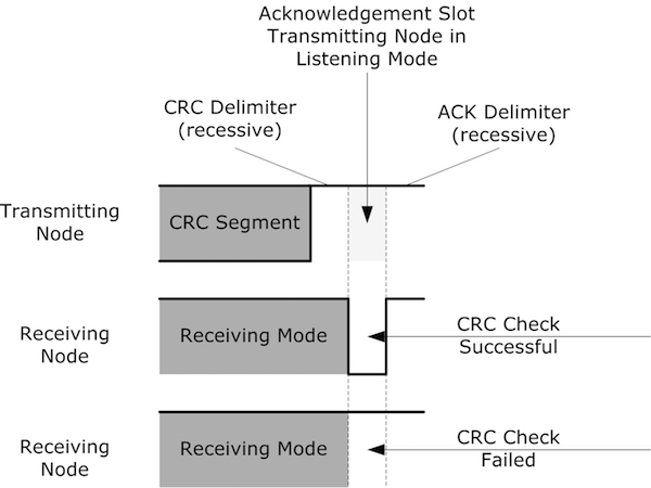
If all nodes in the network determine a checksum error, meaning the sending node monitors a recessive level in the ACK slot, it is clear that the sending node calculated a wrong checksum. The error is therefore local at the sending node.
Any receiving node detecting a checksum error will post an error frame to the bus, i.e., right after the completed acknowledgment field. With this scenario, it is possible to determine whether or not the actual malfunction is with that particular receiving node.
The ACK slot may remain dominant, while at the same time, an error is reported by only one receiving node, meaning this single node will send out an error frame. The error is therefore local at that particular receiving node.
CAN Message Types
- The Data Frame,
- The Remote Frame,
- The Error Frame, and
- The Overload Frame.
The Data Frame is the most common message type. It comprises the following major parts
- The Arbitration Field, which determines the priority of the message when two or more nodes are contending for the bus. The Arbitration Field contains:
- For CAN 2.0A, an 11-bit Identifier and one bit, the RTR bit, which is dominant for data frames.
- For CAN 2.0B, a 29-bit Identifier (which also contains two recessive bits: SRR and IDE) and the RTR bit.
- the Data Field, which contains zero to eight bytes of data.
- the CRC Field, which contains a 15-bit checksum calculated on most parts of the message. This checksum is used for error detection.
- an Acknowledgement Slot; any CAN controller that has been able to correctly receive the message sends an Acknowledgement bit at the end of each message. The transmitter checks for the presence of the Acknowledge bit and re transmits the message if no acknowledge was detected.
important
At a data rate of 1 Mbps, it is possible to send in the order of ten thousand standard format messages per second over a CAN network, assuming an average data length of four bytes. The number of messages that could be sent would come down to around seven thousand if all the messages contained the full eight bytes of data allowed. One of the major benefits of CAN is that, if several controllers require the same data from the same device, only one sensor is required rather than each controller being connected to a separate sensor. As mentioned previously, the data rate that can be achieved is dependent on the length of the bus, since the bit time interval is adjusted upwards to compensate for any increase in the time required for signals to propagate along the bus, which is proportional to the length of the bus. Bus length and bit rate are thus inversely proportional.
The Remote Frame
The intended purpose of the remote frame is to solicit the transmission of data from another node. The remote frame is similar to the data frame, with two important differences. First, this type of message is explicitly marked as a remote frame by a recessive RTR bit in the arbitration field, and secondly, there is no data.
The Identifier field is used to indicate the identifier of the requested message.
• The Data field is always empty (0 bytes).
• The DLC field indicates the data length of the requested message (not the transmitted one
• The RTR bit in the arbitration field is always set to be recessive. However, for a destination node to request data from the source. To accomplish this, the destination node sends a remote frame with an identifier that matches the identifier of the required data frame. The appropriate data source node will then send a data frame in response to the remote frame request. There are two differences between a remote frame (shown in Figure 2-3) and a data frame. First, the RTR bit is at the recessive state and, second, there is no data field. In the event of a data frame and a remote frame with the same identifier being transmitted at the same time, the data frame wins arbitration due to the dominant RTR bit following the identifier. In this way, the node that transmitted the remote frame receives the desired data immediately.
The Error Frame
Simply put, the Error Frame is a special message that violates the framing rules of a CAN message. It is transmitted when a node detects a fault and will cause all other nodes to detect a fault – so they will send Error Frames, too. The transmitter will then automatically try to retransmit the message. There is an elaborate scheme of error counters that ensures that a node can’t destroy the bus traffic by repeatedly transmitting Error Frames.
The Error Frame consists of an Error Flag, which is 6 bits of the same value (thus violating the bit-stuffing rule) and an Error Delimiter, which is 8 recessive bits. The Error Delimiter provides some space in which the other nodes on the bus can send their Error Flags when they detect the first Error Flag.
Consequently, nodes store and track the number of errors detected. A node may be in one of three modes depending on the error count: If the count in either the transmit or receive buffer of a node is greater than zero and less than 128, the node is considered “error active,” indicating that, although the node remains fully functional, at least one error has been detected. An error count between 128 and 255 puts the node in “error passive” mode.
An error passive node will transmit at a slower rate by sending 8 recessive bits before transmitting again or recognizing the bus to be idle. Error counts above 255 will cause the node to enter “bus off” mode, taking itself off-line. Receive errors increment the error count by 1; transmit errors increment the count by 8. Subsequent error-free messages decrement the error count by 1. If the error count returns to zero, a node will return to normal mode. A node in the bus off condition may become error active after 128 occurrences of 11 consecutive recessive bits have been monitored. A message is considered valid by the transmitter if
there is no error until the EOF. Corrupted messages are automatically retransmitted as soon as the bus is idle
The Overload Frame
If a CAN node receives messages faster than it can process them, then an Overload Frame will be generated to provide extra time between successive Data or Remote frames. Similar to an Error Frame, the Overload Frame has two fields: an overload flag consisting of six dominant bits, and an overload delimiter consisting of eight recessive bits. Unlike error frames, error counters are not incremented. The Interframe Space consists of a three recessive bit Intermission and the bus idle time between Data or Remote Frames. During the intermission, no node is permitted to initiate a transmission (if a dominant bit is detected during the Intermission, an Overload Frame will be generated). The bus idle time lasts until a node has something to transmit, at which time the detection of a dominant bit on the bus signals a SOF.
https://copperhilltech.com/blog/controller-area-network-can-bus-tutorial-message-frame-format
