Message Addressing And Identification
It is worth noting once again that there is no explicit address in the CAN messages. Each CAN controller will pick up all traffic on the bus, and using a combination of hardware filters and software, determine if the message is “interesting” or not.
In fact, there is no notion of message addresses in CAN. Instead, the contents of the messages is identified by an identifier which is present somewhere in the message. CAN messages are said to be “contents-addressed”.
A conventional message address would be used like “Here’s a message for node X”. A contents-addressed message is like “Here’s a message containing data labeled X”. The difference between these two concepts is small but significant.
The contents of the Arbitration Field is, per the Standard, used to determine the message’s priority on the bus. All CAN controllers will also use the whole (some will use just a part) of the Arbitration Field as a key in the hardware filtration process.
The Standard does not say that the Arbitration Field must be used as a message identifier. It’s nevertheless a very common usage.
CAN Error Handling
Error handling is built into in the CAN protocol and is of great importance for the performance of a CAN system. The error handling aims at detecting errors in messages appearing on the CAN bus, so that the transmitter can retransmit an erroneous message. Every CAN controller along a bus will try to detect errors within a message. If an error is found, the discovering node will transmit an Error Flag, thus destroying the bus traffic. The other nodes will detect the error caused by the Error Flag (if they haven’t already detected the original error) and take appropriate action, i.e. discard the current message.
Error Detection Mechanisms
The CAN protocol defines no less than five different ways of detecting errors. Two of these works at the bit level, and the other three at the message level.
- Bit Monitoring.
- Bit Stuffing.
- Frame Check.
- Acknowledgement Check.
- Cyclic Redundancy Check.
Bit Monitoring
Each transmitter on the CAN bus monitors (i.e. reads back) the transmitted signal level. If the bit level actually read differs from the one transmitted, a Bit Error is signaled. (No bit error is raised during the arbitration process.)
Bit Stuffing
When five consecutive bits of the same level have been transmitted by a node, it will add a sixth bit of the opposite level to the outgoing bit stream. The receivers will remove this extra bit. This is done to avoid excessive DC components on the bus, but it also gives the receivers an extra opportunity to detect errors: if more than five consecutive bits of the same level occurs on the bus, a Stuff Error is signaled.
Stuffing ensures that rising edges are available for on-going synchronization of the network. Stuffing also ensures that a stream of bits are not mistaken for an error frame, or the seven-bit interframe space that signifies the end of a message. Stuffed bits are removed by a receiving node’s controller before the data is forwarded to the application.
Acknowledgement Check
All nodes on the bus that correctly receives a message (regardless of their being “interested” of its contents or not) are expected to send a dominant level in the so-called Acknowledgement Slot in the message. The transmitter will transmit a recessive level here. If the transmitter can’t detect a dominant level in the ACK slot, an Acknowledgement Error is signaled.
Frame check
Some parts of the CAN message have a fixed format, i.e. the standard defines exactly what levels must occur and when. (Those parts are the CRC Delimiter, ACK Delimiter, End of Frame, and also the Intermission, but there are some extra special error checking rules for that.) If a CAN controller detects an invalid value in one of these fixed fields, a Form Error is signaled
This check looks for fields in the message which must always be recessive bits. If a dominant bit is detected, an error is generated. The bits checked are the SOF, EOF, ACK delimiter, and the CRC delimiter bits
Cyclic Redundancy Check (CRC)
The CRC safeguards the information in the frame by adding redundant check bits at the transmission end. At the receiver end these bits are re-computed and tested against the received bits. If they do not agree there has been a CRC error.
Error Confinement Mechanisms
Nodes that transmit messages on a CAN network will monitor the bus level to detect transmission errors, which will be globally effective. In addition, nodes receiving messages will monitor them to ensure that they have the correct format throughout, as well as recalculating the CRC to detect any transmission errors that have not previously been detected (i.e. locally effective errors). The CAN protocol also has a mechanism for detecting and shutting down defective network nodes, ensuring that they cannot continually disrupt message transmission.
When errors are detected, either by the transmitting node or a receiving node, the node that detects the error signals an error condition to all other nodes on the network by transmitting an error message frame containing a series of six consecutive bits of the dominant polarity. This triggers an error, because the bit-stuffing used by the signalling scheme means that messages should never have more than five consecutive bits with the same polarity (when bit-stuffing is employed, the transmitter inserts a bit of opposite polarity after five consecutive bits of the same polarity. The additional bits are subsequently removed by the receiver, a process known as de-stuffing). All network nodes will detect the error message and discard the offending message (or parts thereof, if the whole message has not yet been received). If the transmitting node generates or receives an error message, it will immediately thereafter attempt to retransmit the message
Each node maintains two error counters: the Transmit Error Counter and the Receive Error Counter. There are several rules governing how these counters are incremented and/or decremented.
In essence, a transmitter detecting a fault increments its Transmit Error Counter faster than the listening nodes will increment their Receive Error Counter. This is because there is a good chance that it is the transmitter who is at fault!
A node starts out in Error Active mode. When any one of the two Error Counters raises above 127, the node will enter a state known as Error Passive and when the Transmit Error Counter raises above 255, the node will enter the Bus Off state.
- An Error Active node will transmit Active Error Flags when it detects errors.
- An Error Passive node will transmit Passive Error Flags when it detects errors.
- A node which is Bus Off will not transmit anything on the bus at all.
When an error is detected, the node transmits an error frame on the bus and increases either its transmit error counter (TEC), or receive error counter (REC). Crucially, a node detecting an error during transmission increases its TEC by 8, whereas a node detecting an error when receiving only increases its REC by 1.
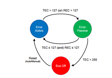
To confine serious errors, each ECU moves between three states as shown above: error active, error passive, and bus off. An ECU starts in error active mode. If either of its TEC or REC counters go above 127, it moves into the error passive mode. An error-passive node returns to error active once both of its TEC and REC counters fall below 128.
When TEC exceeds the limit of 255, the corresponding ECU – which must have triggered many transmit errors – enters the bus-off mode. Upon entering this mode, to protect the CAN bus from continually being distracted, the error-causing ECU is forced to shut down and not participate in sending/receiving data on the CAN bus at all. It can be restored back to its original error active mode either automatically or manually
Message Filtering and Reception
Controllers have one or more data registers (commonly defined as Rx Objects) in which they store the content of the CAN messages received from the bus. Given that the protocol has no destination address field, the transmission semantics are the following. All transmissions are broadcasted, and nodes need a way to select the messages they are interested in receiving. This selection is based on the Identifier value of the frame, which not only defines the frame priority, but also gives information about the message content. Nodes can define one or more message filters (typically one filter associated with each Rx Object) and one or more reception masks to declare the message identifiers they are interested in. Masks can be individually associated to Rx Objects, but most often they are associated to a group of them (or all of them). A reception mask specifies on which bits of the incoming message identifier the filters should operate to detect a possible match A bit at 1 in the mask register usually enables comparison between the bits of the filter and the received id in the corresponding positions. A bit at 0 means don’t care or don’t match with the filter data. In the example in the figure, the id transmitted on the bus is 01110101010 (0x3AA). Given the mask configuration, only the first, third, sixth, seventh and eight bit are going to be considered for comparison with the reception filters.

Bus Termination
An ISO 11898 CAN bus must be terminated. This is done using a resistor of 120 Ohms in each end of the bus. The termination serves two purposes:
- Remove the signal reflections at the end of the bus.
- Ensure the bus gets correct DC levels.
Note that other physical layers, such as “low-speed CAN”, single-wire CAN, and others, may or may not require termination. But your vanilla high-speed ISO 11898 CAN bus will always require at least one terminator.
Different Physical Layers
A physical layer defines the electrical levels and signaling scheme on the bus, the cable impedance and similar things.
There are several different physical layers:
- The most common type is the one defined by the CAN standard, part ISO 11898-2, and it’s a two-wire balanced signaling scheme. It is also sometimes known as “high-speed CAN”.
- Another part of the same ISO standard, ISO 11898-3, defines another two-wire balanced signaling scheme for lower bus speeds. It is fault tolerant, so the signaling can continue even if one bus wire is cut or shorted to ground or Vbat. It is sometimes known as “low-speed CAN”.
- SAE J2411 defines a single-wire (plus ground, of course) physical layer. It’s used chiefly in cars – e.g. GM-LAN.
CAN-FD
Why CAN FD Needed
When a CAN Bus standard was defined by Bosch in 1980 the Electronic Components were few The payload on Network did not go beyond 8 Byte.
The Data rate required for software Flashing was also not very high as software still did not control lot of vehicles
But Now No. of ECU’s to complexity of automotive software everything has scaled upto newer heights. The Bandwidth requirement of new automotive application has been increasing more than gradually This is mainly due to volume variety and Velocity of data from sensor being feed to in vehicle N/w of Control Unit
Automotive ECU Reprogramming is another area Where large Size Binary Files are required to transfer Over in Vehicle N/w
The Bit Rate & Payload Limitation of CAN Standard impending activities like automotive ECU Flashing and Faster Communication For ADAS Application. So high data rate & larger Payload were achieved by Modifying the frame format of CAN This New Frame Format ( CAN FD Solution) has the capability to support higher Bw than 1Mbits/s and hence it could manage Payload Higher than 8Bytes
New Format Soln has the ability to support Flexible Data rate Up to 8Mbps/s
WHAT IS CAN FD?
The CAN FD protocol was pre-developed by Bosch (with industry experts) and was released in 2012. The improved protocol overcomes to CAN limits: You can transmit data faster than with 1 Mbit/s and the payload (data field) is now up to 64 byte long and not limited to 8 byte anymore. In general, the idea is simple: When just one node is transmitting, the bit-rate can be increased, because no nodes need to be synchronized. Of course, before the transmission of the ACK slot bit, the nodes need to be re-synchronized.
1# INCREASED DATA LENGTH
CAN FD supports up to 64 data bytes per data frame vs. 8 data bytes for Classical CAN. This reduces the protocol overhead and leads to an improved protocol efficiency.

2# INCREASED SPEED
CAN FD supports dual bit rates: The nominal (arbitration) bit-rate limited to 1 Mbit/s as given in Classical CAN – and the data bit-rate, which depends on the network topology and transceivers. In practice, data bit-rates up to 5 Mbit/s are achievable.
3# SMOOTH TRANSITION
CAN FD and Classical CAN only ECUs can be mixed under certain conditions. This allows for a gradual introduction of CAN FD nodes, greatly reducing costs and complexity for OEMs.
In practice, CAN FD can improve network bandwidth by 3-8x vs Classical CAN, creating a simple solution to the rise in data.
But why not speed up the entire CAN message (rather than just the data phase)?
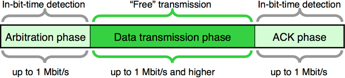
This is due to “arbitration”: If 2+ nodes transmit data simultaneously, arbitration determines which node takes priority. The “winner” continues sending (without delay), while the other nodes “back off” during the data transmission.
During arbitration, a “bit time” provides sufficient delay between each bit to allow every node on the network to react. To be certain that every node is reached within the bit time, a CAN network running at 1 Mbit/s needs to have a maximum length of 40 meters (in practice 25 meters). Speeding up the arbitration process would reduce the maximum length to unsuitable levels.
On the other hand, after arbitration there’s an “empty highway” – enabling high speed during the data transmission (when there is just one node driving the bus-lines). Before the ACK slot – when multiple nodes acknowledge the correct reception of the data frame – the speed needs to be reduced to the nominal bit-rate.
So in short we need a way to only increase the speed during the data transmission.
CAN vs CAN FD: Compatibility
One of the main questions about CAN FD is rather or not it will work with a standard CAN network. The answer is probably not.
One of the main problems with CAN and CAN FD compatibility is that they are very close but not the same. One of the main differences is that during the data transmission phase, the FD frame will accelerate the data rate. However, because the frame started off looking like a valid CAN frame, the standard CAN controller is receiving it. When it goes into accelerated data rate, the standard CAN frame will not see stuff bits and think that data bus is broken. It will then reject the frame with an error frame.
This is not the case in reverse, a CAN FD controller will be able to receive a standard CAN frame with no problems. Going forward, there will be CAN FD tolerant standard CAN controllers. They will know that a CAN FD frame is going and ignore it without sending an error frame. But, the main conclusion is that using CAN FD on a legacy CAN bus is not a good idea and will almost certainly not work.
CANFD Frame Format
Using a ratio of 1:8 for the bit-rates in the arbitration and data phase leads to an approximately six-times higher throughput considering that the CAN FD frames use more bits in the header (control field) and in the CRC field.
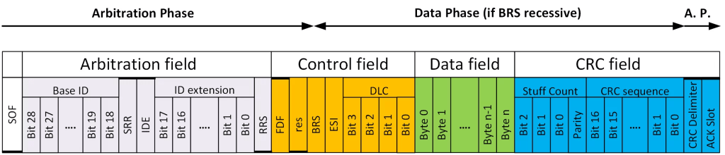
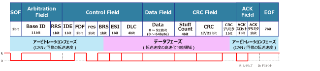
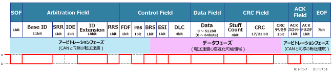
CAN FD data frames with 11-bit identifiers use the FBFF (FD base frame format) and those with 29-bit identifiers use the FEFF (FD extended frame format). The CAN FD protocol doesn’t support remotely requested data frames.
There are three main differences between CAN FD and Classical CAN: Bit Rate Switching (BRS); maximum size of the data payload; the coverage of the CRC.
BIT Rate Switching
In a classical CAN frame, all the data is sent at one bit rate. This can be from 10kHz up to 1MHz and is always one fixed bit rate. In CAN FD, the FD stands for Flexible Data rate. This means that two different bit rates can be used in one CAN FD frame. These bit rates are fixed for one frame and one network and cannot be changed in any dynamic way. Just like in classical CAN, a system is designed for a specific bit rate, but in CAN FD you can have two different bit rates for different parts of the frame. This feature is called Bit Rate Switching (BRS) and is enabled by a new control bit called BRS, added to the existing control bits between the CAN ID and the Data Length Code (DLC).
Do we need to make any change in Network if we don’t change BRS.
It is important to understand that a CAN FD network does not have to enable BRS. It is perfectly acceptable to use CAN FD at one fixed bit rate, with the Nominal bit rate and the Data bit rate at equal values. If you upgrade a network to CAN FD and use the nominal bit rate only, the physical network remains the same. A system like this would still give you two of the three CAN FD advantages; larger data payloads and improved CRC coverage. In a system that is not bandwidth limited, it would be perfectly acceptable to upgrade to CAN FD for the longer data payloads and/or the added safety and security of the improved CRC and leave BRS disabled so that no change to the physical wiring would be required.
What’s called the Arbitration phase (refer to the CAN Bus Protocol Tutorial) is transmitted at the nominal bit rate, and if the BRS control bit is enabled (set to one, recessive) the Data phase is transmitted at a higher bit rate, the data bit rate. If you remember back to the CAN Bus Protocol Tutorial there are two main parts of the CAN frame, the Arbitration phase and the Data phase. In classical CAN the entire frame is sent at one fixed bit rate. In CAN FD the Data phase will be sent at a higher bit rate if the BRS bit is enabled. This higher bit rate is typically two to eight times as fast as the nominal bit rate.
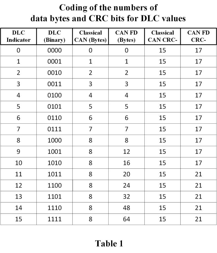
Data Length Codes up to 64 bytes of data
Classical CAN frames can transmit between zero and eight bytes of data in the Data phase. Eight bytes is the maximum amount of data, sometimes referred to as the maximum data payload, in a Classical CAN frame. CAN FD increases this maximum payload to sixty-four (64) bytes. This significant increase in data payload enables CAN FD to be so much more efficient than classical CAN. There is one catch with this increase. In both classical CAN and CAN FD there are four control bits, called Data Length Code (DLC), that indicate the size of the data payload. The first eight bytes of data are mapped one-to-one to the DLC value, so the DLC directly indicates the number of data bytes in the data phase if there are zero to eight bytes of data. When you get above eight bytes of data in the frame, you must use a standard size frame, and the size is no longer directly mapped to the DLC value on a one-to-one basis. The table below will make this clear and shows the relationship between DLC and the size of the data payload for both Classical CAN and CAN FD.
Different types of CAN and CAN FD frames
CBFF – Classical Base Frame Format: Original CAN with an 11-bit ID and 0 to 8 bytes of data.
CEFF – Classical Extended Frame Format: Original CAN with a 29-bit ID and 0 to 8 bytes of data.
FBFF – FD Base Frame Format: CAN FD with an 11-bit ID and up to 64 bytes of data.
FEFF – FD Extended Frame Format: CAN FD with a 29-bit ID and up to 64 bytes of data.
A look at the new control bits in CAN FD
Substitute Remote Request (SRR)
This bit is only defined for Extended frames (IDE=1) and has a different use in the Base frame when IDE=0. For the 29-bits frame formats CEFF and FEFF where IDE=1, this bit substitutes the RTR-bit in CBFF and the RRS-bit in the FBFF. This bit is always sent recessive (SRR=1) for both frame formats. CAN FD receivers will accept SRR=0 without triggering a form error.
IDentifier Extension (IDE)
Unlike the bits I have described above, the IDE bit is always called the same thing, and it is always transmitted in the same time slot. For both the CBFF and FBFF, the IDE bit is dominant. That means for any Base Frame Format, that is any frames with an eleven-bit ID, IDE is dominant. For both CEFF and FEFF the IDE bit is recessive. That means for any Extended Frame Format, that is any frame with a twenty-nine-bit ID, IDE is recessive.
Remote Request Substitution (RRS)
Both CBFF and CEFF support RTR (Remote Transmission Request) which is indicated by a recessive bit (RTR=1) after the last ID bit. When an ordinary data frame is sent, this bit will be sent as dominant (RTR=0). In CAN FD remote request is not supported, and all CAN FD frames are data frames, which for Classical frames are indicated by dominant (RTR=0) bit. To indicate the different use in the CAN FD frames, this bit is named Remote Request Substitution (RRS). The RRS-bit is always sent dominant (RRS=0) because a CAN FD frame is always a data frame. CAN FD receivers will accept RRS as recessive (RRS=1) without triggering a form error.
FD Format indicator (FDF)
This is the bit that distinguishes between classical CAN and CAN FD frames. It is dominant in the classical CAN frame formats (CBFF and CEFF), and recessive in the CAN FD frame formats (FBFF and FEFF). The FDF bit is not always transmitted in the same time slot. In the Base frame formats (CBFF and FBFF) the FDF bit is transmitted in the control field just after the IDE bit. Because the arbitration field is extended in frames with 29-bit identifiers (CEFF and FEFF), the FDF bit is transmitted after the RTR or RRS bits respectively in extended frame formats. This keeps it in the control field, so it is never included in arbitration.
Reserved bit in FD Frames (res)
This bit is only present in CAN FD frames and is always transmitted as dominant. It is reserved for future use and will most likely be used in CAN XL (the subject of a later protocol tutorial). Since it is transmitted as part of the control field it is not used in arbitration. It is interesting to note that it is called the r0 bit only in classical extended frames (CEFF), but still transmitted in the same state as dominant. The reason for the naming differences, and really for the existence of this bit, is for backward compatibility with previous versions of ISO 11898.
Bit Rate Switch (BRS)
This is a bit that is completely new to CAN FD, and did not exist in classical CAN. One of the big advantages of CAN FD is that the bit rate can be increased up to 8 Mbps after the arbitration field is transmitted. BRS is part of the control field, always transmitted just after the res bit. It indicates whether the bit rate is going to stay the same or switch up to a faster rate. The arbitration field is always transmitted at the nominal bit rate, and if BRS is recessive the bit rate will switch up to a higher data bit rate at the sample point of the BRS bit. So BRS is unique; it is the only bit whose state determines a timing shift at its own sample point. If BRS is sampled as recessive the bit rate will switch to the data bit rate, and sample points will have to switch accordingly. If BRS is sampled as dominant, the bit rate will remain the same for the rest of the CAN FD frame. Figure 2 is a representation of the control field that clearly shows the location of the sample point of BRS and the resulting change in bit timing from an active BRS.
Error State Indicator (ESI)
This is also a new bit only used in CAN FD. The ESI bit is used by a CAN FD node to indicate that it is in an error active state. By transmitting ESI as dominant, a node is indicating that it is in the error active state, and by transmitting it as recessive the same node indicates an error passive state. ESI is always transmitted in the control field, just after BRS. This means it is the first bit to be transmitted at the data bit rate in all CAN FD frames with BRS enabled.
CRCs of 17 and 21 bits, and increased error detection coverage
In most communication protocols there is a block of bits, usually transmitted after everything else in the frame, called the Cyclic Redundancy Check (CRC). The CRC is not unique to CAN or CAN FD, it is used in many digital communication protocols. There is plenty of good information out there on the concept of CRCs, including entire books written on the concept alone. Classical CAN uses a 15-bit CRC and doesn’t include the stuff bits. CAN FD uses either a 17-bit CRC for data fields up to and including 16 bytes, or a 21-bit CRC for data fields 20 bytes and over. CAN FD also includes the stuff bits in the CRC calculation, and adds a 3-bit stuff count to be transmitted at the beginning of the CRC. Because of the larger data phase available in CAN FD, these changes are required to give CAN FD comparable error detection capability to that of classical CAN.
The CRC Delimiter is transmitted just after the last bit in the CRC sequence. When a CAN FD node reaches the sample point of the CRC delimiter, it switches from the data bit rate back to the nominal bit rate. This change can be seen in Figure 3, where the recessive CRC delimiter is a little longer than the data bits, and the dominant Acknowledge bit is displayed at the nominal bit rate.
Acknowledge Bit
The Acknowledge (ACK) bit is shown furthest to the right in Figure 5. It’s shown as recessive, although if you look at Figure 3 you see it as the last dominant bit in the frame. It is shown as recessive in Figure 5 because it is transmitted as recessive by the node that has transmitted the frame. It is the other nodes, all receivers on the network, that drive the ACK bit to dominant, just like in classical CAN. It only takes one node to drive the bus dominant, so what the ACK bit tells the transmitting node as it finishes transmitting a frame, is that at least one receiver has confirmed reception of the frame.
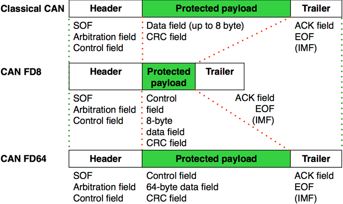
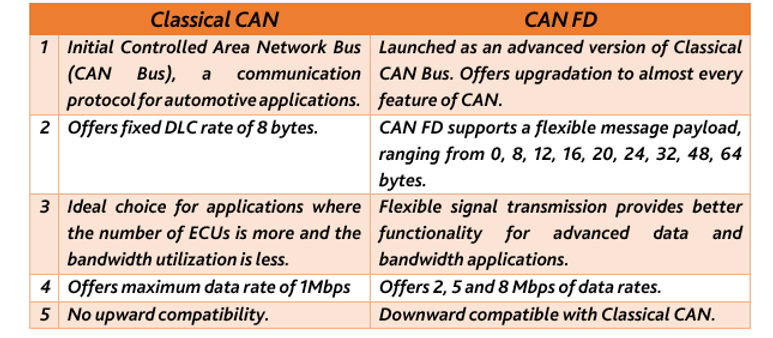
Comparison between Classical CAN and CANFD.
Reference *
