History:
- On May 22, 1973, while working at the Xerox Palo Alto Research Center (PARC) in California, Bob Metcalfe wrote a memo describing the network system he had invented for interconnecting advanced computer workstations called Xerox Altos.
- The era of open computer communications based on Ethernet technology formally began in 1980 when the Digital Equipment Corporation (DEC), Intel, and Xerox (DIX) consortium announced the first standard for 10 Mb/s Ethernet.
- Ethernet was reinvented to increase its speed by a factor of 10. Based on technology developed by Grand Junction Networks (later acquired by Cisco Systems), the new standard created the 100 Mb/s Fast Ethernet system, which was formally adopted in 1995
- In 1998, Ethernet was reinvented again, this time to increase its speed by another factor of 10. The Gigabit Ethernet standard describes a system that operates at the speed of 1 billion bits per second over fiber optic and twisted-pair media.
The features of Ethernet are as follows:
- Through Ethernet network, data can be sent and received at very high speed.
- Ethernet network is less expensive.
- With the help of Ethernet networking, your data is secured as it protected your data. Suppose that someone is attempting on your network, and then all of the devices in your network stop processing instantly and wait until the user attempts to transmit it again.
- Ethernet facilitates us to share our data and resources like printers, scanners, computers etc. Ethernet network quickly transmits the data. That’s why, nowadays most of the universities and college campuses make use of Ethernet technology, which is based upon the Gigabit Ethernet.
Advantages of using wired Ethernet network
• It is very reliable.
• Ethernet network makes use of firewalls for the security of the data.
• Data is transmitted and received at very high speed.
• It is very easy to use the wired network.
Disadvantages of using wired Ethernet network
• The wired Ethernet network is used only for short distances.
• The mobility is limited.
• Its maintenance is difficult.
• Ethernet cables, hubs, switches, routers increase the cost of installation.
Types of Ethernet network
The maximum data rate of the original Ethernet technology is 10 megabits per second (Mbps), but a second generation fast ethernet carries 100 Mbps, and the latest version called gigabit ethernet works at 1000 Mbps. Ethernet network can be classified into 3 types:
- Standard Ethernet: 10 Mbps
- Fast Ethernet: 100 Mbps
- Gigabit Ethernet: 1,000 Mbps
The IEEE has assigned shorthand identifiers to the various Ethernet media systems as they have been developed. The three-part identifiers include the speed, the type of signaling used, and information about the physical medium.
Standard Ethernet Code
Guide to Ethernet Coding
| 10 | at the beginning means the network operates at 10Mbps. |
| BASE | means the type of signaling used is baseband. Not Broadband “Base” (short for “baseband”) indicates the type of network transmission that the cable uses. Baseband transmissions carry one signal at a time and are relatively simple to implement. The alternative to baseband is broadband, which can carry more than one signal at a time but is more difficult to implement. At one time, broadband incarnations of the 802.x networking standards existed, but they have all but fizzled due to lack of use. The tail end of the designation indicates the cable type. For coaxial cables, a number is used that roughly indicates the maximum length of the cable in hundreds of meters. 10Base5 cables can run up to 500 meters. 10Base2 cables can run up to 185 meters. (The IEEE rounded 185 up to 200 to come up with the name 10Base2.) If the designation ends with a T, twisted-pair cable is used. Other letters are used for other types of cables. |
| 2 or 5 | at the end indicates the maximum cable length in meters. |
| T | the end stands for twisted-pair cable. |
| X | at the end stands for full duplex-capable cable. |
| FL | at the end stands for fiber optic cable. |
For example: 100BASE-TX indicates a Fast Ethernet connection (100 Mbps) that uses a
twisted pair cable capable of full-duplex transmissions.
In the earliest Ethernet media systems, the physical medium part of the identifier was based on the cable distance in meters (m), rounded to the nearest 100 meters. In the more recent media systems, the IEEE engineers dropped the distance convention, and the third part of the identifier, which is indicated by a dash (-), simply identifies the media type used (twisted-pair or fiber optic). In roughly chronological order, the identifiers include the following set.
10 Base2

An earlier 10 Mbps Ethernet standard that used a thin coaxial cable. Network nodes were attached to the cable via T-type BNC connectors in the adapter cards. Also called “thin Ethernet,” “ThinWire,” “ThinNet” and “Cheapernet,
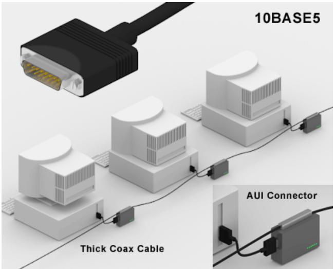
- 10BASE5
This identifies the original Ethernet system, based on thick coaxial cable. The identifier means 10 megabits per second transmission speed, baseband transmission; the 5 refers to the 500-meter maximum length of a given cable segment. The word baseband in this instance means that the transmission medium, thick coaxial cable, is dedicated to carrying one service 10BASE5 uses a thick and stiff coaxial cable up to 500 metres
Network nodes attached via an “AUI interface” to transceivers that tapped into the bus. Also called “thick Ethernet,” “ThickWire” and “ThickNet,”
- 10BASE-T
The “T” in this identifier stands for “twisted,” as in twisted-pair wires. This variety of the Ethernet system operates at 10 Mb/s, in baseband mode, over two pairs of Category 3 (or better) twisted-pair wires.[11] A hyphen is used in this and all newer media identifiers to distinguish the older “length” designators from the newer “media type” designators
10Base-T Ethernet (“T” means twisted) was easier to install than previous “thick” and “thin” Ethernets that used coaxial cable.
All stations in a 10Base-T and 100Base-T Ethernet are wired to a central hub or switch using twisted pair wires and RJ-45 connectors . 10 Mbps with category 3 unshielded twisted pair (UTP) wiring, up to 100 meters long

- 100BASE-TX
This standard describes a Fast Ethernet system that operates at 100 Mb/s, in baseband mode, over two pairs of Category 5 twisted-pair cables. The TX identifier indicates that this is the twisted-pair version of the 100BASE-X media systems. This is the most widely used variety of Fast Ethernet.
Cabling Types
An important part of designing and installing an Ethernet is selecting the appropriate Ethernet medium. There are four major types of media in use today: Thickwire for 10BASE5 networks; thin coax for 10BASE2 networks; unshielded twisted pair (UTP) for 10BASE-T networks; and fiber optic for 10BASE-FL or Fiber-Optic Inter-Repeater Link (FOIRL) networks
Unshielded Twisted Pair
Thicknet Uses a thick coaxial cable (no longer used in today’s networks)
![]() Thinnet Uses a thin coaxial cable (no longer used in today’s networks)
Thinnet Uses a thin coaxial cable (no longer used in today’s networks)
![]() Unshielded twisted pair (UTP) Uses a four-pair wire, where each pair is periodically twisted
Unshielded twisted pair (UTP) Uses a four-pair wire, where each pair is periodically twisted

The most popular wiring schemes are 10BASE-T and 100BASE-TX, which use unshielded twisted pair (UTP) cable. This is similar to telephone cable and comes in a variety of grades, with each higher grade offering better performance. Level 5 cable is the highest, most expensive grade, offering support for transmission rates of up to 100 Mbps. Level 4 and level 3 cable are less expensive, but cannot support the same data throughput speeds; level 4 cable can support speeds of up to 20 Mbps; level 3 up to 16 Mbps.
UTP’s internal copper cables are either 22- or 24-gauge in diameter. UTP for Ethernet has 100-ohm impedance, so you can’t use just any UTP wiring, such as that commonly found for telephones, for example. Each of the eight wires inside the cable is colored: some solid, some striped. Two pairs of the wires carry a true voltage, commonly called “tip” (T1–T4), and the other four carry an inverse voltage, commonly called “ring” (R1–R4). Today, people commonly call these positive and negative wires, respectively. A pair consists of a positive and negative wire, such as T1 and R1, T2 and R2, and so on, where each pair is twisted down the length of the cable.
Cable Grade Capabilities
| Cable Name | Makeup | Frequency Support | Data Rate | Network Compatibility |
| Cat-5 | 4 twisted pairs of copper wire — terminated by RJ45 connectors | 100 MHz | Up to 1000Mbps | ATM, Token Ring,1000Base-T, 100Base-TX, 10Base-T |
| Cat-5e | 4 twisted pairs of copper wire — terminated by RJ45 connectors | 100 MHz | Up to 1000Mbps | 10Base-T, 100Base-TX, 1000Base-T |
| Cat-6 | 4 twisted pairs of copper wire — terminated by RJ45 connectors | 250 MHz | 1000Mbps | 10Base-T, 100Base-TX, 1000Base-T |
The two endpoints of a UTP cable have an RJ-45 connector. The RJ-45 connector is a male connector that plugs into a female RJ-45 receptacle. The RJ-45 connector is similar to what you see on a telephone connector (RJ-11), except that the RJ-45 is about 50 percent larger in size.As mentioned earlier, the UTP cable has eight wires in it (four pairs of wires). Two types of implementations are used for the pinouts of the two sides of the wiring: straight-through and crossover.
There are two kinds of Ethernet cables you can make, Straight Through and Crossover.
A straight-through Ethernet UTP cable has pin 1 on one side connected to pin 1 on the other side, pin 2 to pin 2, and so on. A straight-through cable is used for DTE-to-DCE (data termination equipment to data communications equipment) connections.
Straight-through connections


A crossover UTP Ethernet cable crosses over two sets of wires: pin 1 on one side is connected to pin 3 on the other side, and pin 2 is connected to pin 6. Crossover cables should be used when you connect a DTE device to another DTE device or a DCE to another DCE.

| Designation | Supported Media | Maximum Segment Length | Transfer Speed | Topology |
| 10Base-5 | Coaxial | 500m | 10Mbps | Bus |
| 10Base-2 | ThinCoaxial (RG-58 A/U) | 185m | 10Mbps | Bus |
| 10Base-T | Category3 or above unshielded twisted-pair (UTP) | 100m | 10Mbps | Star,using either simple repeater hubs or Ethernet switches |
| 1Base-5 | Category3 UTP, or above | 100m | 1Mbps | Star,using simple repeater hubs |
| 10Broad-36 | Coaxial(RG-58 A/U CATV type) | 3600m | 10Mbps | Bus(often only point-to-point) |
| 10Base-FL | Fiber-optic- two strands of multimode 62.5/125 fiber | 2000m (full-duplex) | 10Mbps | Star(often only point-to-point) |
| 100Base-TX | Category5 UTP | 100m | 100Mbps | Star,using either simple repeater hubs or Ethernet switches |
| 100Base-FX | Fiber-optic- two strands of multimode 62.5/125 fiber | 412 meters (Half-Duplex) 2000 m (full-duplex) | 100 Mbps (200 Mb/s full-duplex mode) | Star(often only point-to-point) |
| 1000Base-SX | Fiber-optic- two strands of multimode 62.5/125 fiber | 260m | 1Gbps | Star,using buffered distributor hub (or point-to-point) |
| 1000Base-LX | Fiber-optic- two strands of multimode 62.5/125 fiber or monomode fiber | 440m (multimode) 5000 m (singlemode) | 1Gbps | Star,using buffered distributor hub (or point-to-point) |
| 1000Base-CX | Twinax,150-Ohm-balanced, shielded, specialty cable | 25m | 1Gbps | Star(or point-to-point) |
| 1000Base-T | Category5 | 100m | 1Gbps | Star |
Types of Network Topology
Network Topology is the schematic description of a network arrangement, connecting various nodes(sender and receiver) through lines of connection.
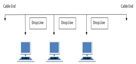
- BUS Topology
Bus topology is a network type in which every computer and network device is connected to single cable. When it has exactly two endpoints, then it is called Linear Bus topology.
Maximum segment length of 200M
Maximum no of connections 30 Devices
Four repeaters may be used to total cable length of 1000m
Features of Bus Topology
- It transmits data only in one direction.
- Every device is connected to a single cable
Advantages of Bus Topology
- It is cost effective.
- Cable required is least compared to other network topology.
- Used in small networks.
- It is easy to understand.
- Easy to expand joining two cables together.
Disadvantages of Bus Topology
- Cables fails then whole network fails.
- If network traffic is heavy or nodes are more the performance of the network decreases.
- Cable has a limited length.
- It is slower than the ring topology.
RING Topology
It is called ring topology because it forms a ring as each computer is connected to another computer, with the last one connected to the first. Exactly two neighbors for each device.
Features of Ring Topology
- A number of repeaters are used for Ring topology with large number of nodes, because if someone wants to send some data to the last node in the ring topology with 100 nodes, then the data will have to pass through 99 nodes to reach the 100th node. Hence to prevent data loss repeaters are used in the network.
- The transmission is unidirectional, but it can be made bidirectional by having 2 connections between each Network Node, it is called Dual Ring Topology.
- In Dual Ring Topology, two ring networks are formed, and data flow is in opposite direction in them. Also, if one ring fails, the second ring can act as a backup, to keep the network up.
- Data is transferred in a sequential manner that is bit by bit. Data transmitted, has to pass through each node of the network, till the destination node.
Advantages of Ring Topology
- Transmitting network is not affected by high traffic or by adding more nodes, as only the nodes having tokens can transmit data.
- Cheap to install and expand
Disadvantages of Ring Topology
- Troubleshooting is difficult in ring topology.
- Adding or deleting the computers disturbs the network activity.
- Failure of one computer disturbs the whole network.

STAR Topology
In this type of topology all the computers are connected to a single hub through a cable. This hub is the central node and all others nodes are connected to the central node.
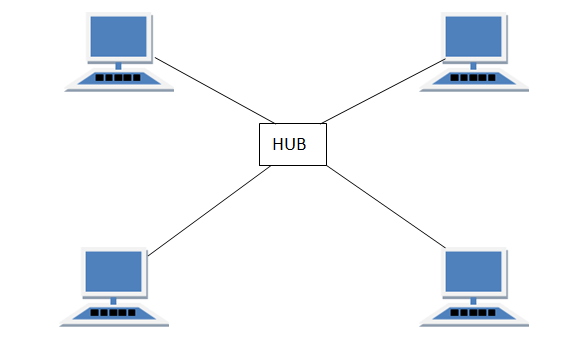
Features of Star Topology
- Every node has its own dedicated connection to the hub.
- Hub acts as a repeater for data flow.
- Can be used with twisted pair, Optical Fibre or coaxial cable.
Advantages of Star Topology
- Fast performance with few nodes and low network traffic.
- Hub can be upgraded easily.
- Easy to troubleshoot.
- Easy to setup and modify.
- Only that node is affected which has failed, rest of the nodes can work smoothly.
Disadvantages of Star Topology
- Cost of installation is high.
- Expensive to use.
- If the hub fails then the whole network is stopped because all the nodes depend on the hub.
- Performance is based on the hub that is it depends on its capacity
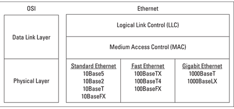
Ethernet Layer Protocol :
Ethernet operates at the first two layers of the OSI model — the Physical and the Data Link layers. However, Ethernet divides the Data Link layer into two separate layers: the Logical Link Control (LLC) layer and the Medium Access Control (MAC) layer
CSMA /CD
- Half-duplex simply means that only one computer can send data over the Ethernet channel at any given time. In half-duplex mode, multiple computers share access to a single Ethernet channel by using the Carrier Sense Multiple Access with Collision Detection (CSMA/CD) Media Access Control (MAC) protocol.
- Full-duplex is a data communications term that refers to the ability to send and receive data at the same time.
CSMA/CD
The acronym CSMA/CD signifies carrier-sense multiple access with collision detection
and describes how the Ethernet protocol regulates communication among nodes. In other words,CSMA/CD is a set of rules determining how network devices respond when two devices attempt to use a data channel simultaneously (called a collision). Standard Ethernet networks use CSMA/CD. This standard enables devices to detect a collision. After detecting a collision, a device waits a random delay time and then attempts to re-transmit the message. If the device detects a collision again, it waits twice as long to try to re-transmit the message.
- After detecting a collision, each device that was transmitting a packet delays a random amount of time before re-transmitting the packet. If another collision occurs, the device waits twice as long before trying to re-transmit.
- The mechanism for preventing packet collision is the Carrier Sense Multiple Access with Collision Detection (CSMA/CD) method specified by the IEEE standard. Prior to data being transmitted, a station must enter Carrier Sense (CS) mode. If no data is detected on the channel, all stations have an equal opportunity to transmit a frame, a condition known as Multiple Access (MA)
- If two or more stations begin transmitting frames and detect that they are transmitting at the same time, a state known as Collision Detection (CD), then the stations halt transmission, enter the CS mode and wait for the next MA opportunity. Collisions can occur because there is a time difference between when two stations might detect MA, depending on their “distance” in the network. When a collision occurs, the frames must be re-sent by their respective parties.
- You might be wondering how, if a CD event occurs, two stations can prevent retransmitting at the same time in the future, thereby repeating their previous collision—the answer is that the delay between retransmission is randomized for each network interface. This prevents repetitive locking, and delivery of a packet will always be attempted 16 times before a failure occurs
Network Devices :
Two or more devices are connected to each other for purpose of sharing data or resources from a network
Hub – A hub is basically a multiport repeater. A hub connects multiple wires coming from different branches, for example, the connector in star topology which connects different stations. Hubs cannot filter data, so data packets are sent to all connected devices.
Unlike a network switch or router, a network hub has no routing tables or intelligence on where to send information and broadcasts all network data across each connection
Types of Hub
- Active Hub:– These are the hubs which have their own power supply and can clean, boost and relay the signal along with the network. It serves both as a repeater as well as wiring centre. These are used to extend the maximum distance between nodes.
- Passive Hub :- These are the hubs which collect wiring from nodes and power supply from active hub. These hubs relay signals onto the network without cleaning and boosting them and can’t be used to extend the distance between nodes.
Repeater – A repeater operates at the physical layer. Its job is to regenerate the signal over the same network before the signal becomes too weak or corrupted so as to extend the length to which the signal can be transmitted over the same network. An important point to be noted about repeaters is that they do not amplify the signal. When the signal becomes weak, they copy the signal bit by bit and regenerate it at the original strength. It is a 2 port device.
Bridge – A bridge operates at data link layer. A bridge is a repeater, with add on functionality of filtering content by reading the MAC addresses of source and destination. It is also used for interconnecting two LANs working on the same protocol. It has a single input and single output port, thus making it a 2 port device.
A network bridge is a device that divides a network into segments. Each segment represent a separate collision domain, so the number of collisions on the network is reduced. Each collision domain has its own separate bandwidth, so a bridge also improves the network performance.
A bridge works at the Data link layer (Layer 2) of the OSI model. It inspects incoming traffic and decide whether to forward it or filter it. Each incoming Ethernet frame is inspected for destination MAC address. If the bridge determines that the destination host is on another segment of the network, it forwards the frame to that segment.
Switch – A switch is a multi port bridge with a buffer and a design that can boost its efficiency(large number of ports imply less traffic) and performance. Switch is data link layer device. Switch can perform error checking before forwarding data, that makes it very efficient as it does not forward packets that have errors and forward good packets selectively to correct port only. In other words, switch divides collision domain of hosts, but broadcast domain remains same. Each switch has a dynamic table (called the MAC address table) that maps MAC addresses to ports. With this information, a switch can identify which system is sitting on which port and where to send the received frame.
Differences between a switch and a bridge
Switches are basically multiport bridges. Although both types of devices perform a similar function, segmenting a LAN into separate collision domains, there are some differences between them:
- most bridges have only 2 or 4 ports. A switch can have hundreds of ports.
- bridges are software based. Switches are hardware-based and use chips (ASICs) when making forwarding decisions, which makes them much faster than bridges.
- switches can have multiple spanning-tree instances. Bridges can have only one.
- switches can have multiple broadcast domains (one per VLAN).
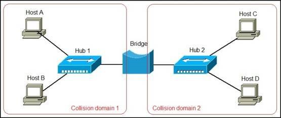
To better understand the difference between a bridge and a switch, consider the following example. Let’s say that we have a network of four computers. First, we will connect them together using a two-port bridge:
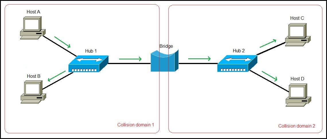
Because the bridge has only two ports, we need to use hubs in order to connect all computers together. Only two collision domains are created. If Host A wants to send a frame to Host C, all computers on the network will receive the frame, since hubs forward the frames out all ports.
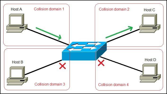
Now consider what happens if we replace the bridge with a switch. Since the switch has plenty of ports, no hubs are necessary. Each port is a separate collision domain and four collision domains are created. If Host A wants to send a frame to Host C, the switch will forward the frame only to Host C. Other hosts on the network will not receive the frame:
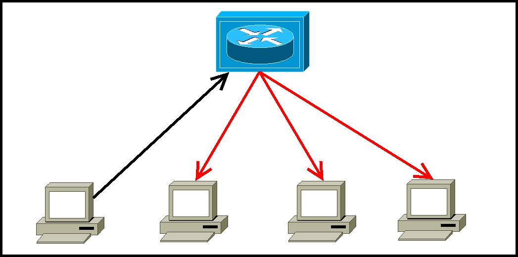
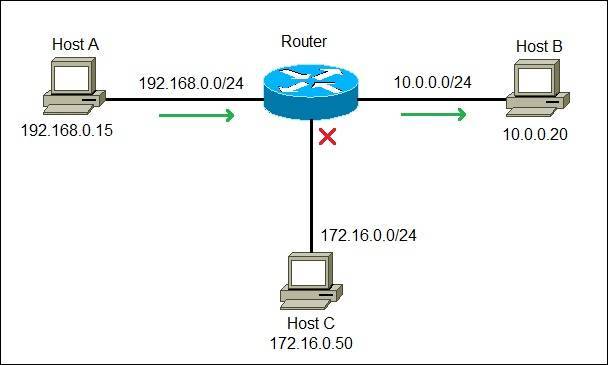
What is a router?
A router is a network device that connects different computer networks by routing packets from one network to the other. This device is usually connected to two or more different networks. When a data packet comes to a router port, the router reads the address information in the packet to determine out which port the packet will be sent. For example, a router provides you with the internet access by connecting your LAN with the Internet.
A router is considered a Layer 3 device of the OSI model because its primary forwarding decision is based on the information of the OSI Layer 3 (the destination IP address). If two hosts from different networks want to communicate with each other, they will need a router between them. Consider the following example:
Just as a switch connects multiple devices to create a network, a router connects multiple switches, and their respective networks, to form an even larger network. These networks may be in a single location or across multiple locations. When building a small business network, you will need one or more routers. In addition to connecting multiple networks together, the router also allows networked devices and multiple users to access the Internet.
Ultimately, a router works as a dispatcher, directing traffic and choosing the most efficient route for information, in the form of data packets, to travel across a network.
The main objective of router is to connect various networks simultaneously and it works in network layer, whereas the main objective of switch is to connect various devices simultaneously and it works in data link layer
Hardware:
There are two basic groups of Ethernet hardware components: the signaling components, used to send and receive signals over the physical medium, and the media components, used to build the physical medium that carries the Ethernet signals. Not surprisingly, these hardware components differ depending on the speed of the Ethernet system and the type of cabling used.
Signaling components
The signaling components for a twisted-pair system include the Ethernet interface located in the computer, a transceiver, and a twisted-pair cable
Media components
The cables and signaling components used to create the signal-carrying portion of an Ethernet channel are part of the physical medium. The physical cabling components vary depending on which kind of media system is in use.
In order to get the network protocol packet to its destination, however, the high-level network protocol software and the Ethernet system must interact to provide the correct destination address for the Ethernet frame
Finding of Ethernet Address
When using TCP/IP, the destination address of the IP packet is used to discover the Ethernet destination address of the station for which the packet is intended. Let’s look briefly at how this works.
The Internet Protocol networking software in a given computer is aware of both the 32-bit IP address assigned to that computer, and the 48-bit Ethernet address of its network interface. However, when first trying to send a TCP/IP packet over the Ethernet, it doesn’t know what the Ethernet addresses of the other stations on the network are.
To make things work, there needs to be a way to discover the Ethernet addresses of other IP-based computers on the local network. The TCP/IP network protocol system accomplishes this task by using a separate protocol called the Address Resolution Protocol (ARP).

Station A has been assigned the 32-bit IP address of 192.0.2.1, and wishes to send data over the Ethernet system to Station B, which has been assigned IP address 192.0.2.2. Station A sends a packet to the broadcast address, containing an ARP request. The ARP request basically says, “Will the station on this Ethernet that has the IP address of 192.0.2.2 please tell me what the 48-bit hardware address of its Ethernet interface is?”
Following the broadcast, only Station B with IP address 192.0.2.2 will respond, sending a packet containing the Ethernet address of that station back to the requesting station. Now Station A has an Ethernet address to which it can send frames containing data destined for Station B, and the high-level protocol communication can proceed.
Ethernet General Terminologies:
- Network interface: This interface — sometimes called a network port — is installed on a computer to enable the computer to communicate over a network. Almost all network interfaces implement a networking standard called Ethernet.
- A network is simply two or more computers, connected, so that they can exchange information (such as email messages or documents) or share resources (say, disk storage or printers)
- Switches: You don’t typically use a network cable to connect computers directly to each other. Instead, each computer is connected by cable to a central switch, which connects to the rest of the network.
- Local area networks (LAN): In this type of network, computers are relatively close together, such as within the same office or building.
- Wide area networks (WAN): These networks span a large geographic territory, such as an entire city or a region or even a countryTopology refers to the way the devices in your network are connected to each other via network switches.
- TCP/IP is the basic networking protocol that your network uses to keep track of the individual computers and other devices on the network. Each computer or device will need an IP address (for example, 10.0.101.65).
- Topology refers to the way the devices in your network are connected to each other via network switches.
- Most Ethernet networks are built using twisted-pair cable (also known as UTP cable)
- Twisted-pair cable comes in various grades, or Categories.
- The higher the number, the faster the data transfer rate, so Cat5 is faster than Cat2
- Most twisted-pair cable has four pairs of wires, for a total of eight wires.
- But today, almost all cabled networks are built using simple copper-based Unshielded Twisted-Pair (UTP) cable. .
- UTP cable consists of four pairs of thin wire twisted around each other; several such pairs are gathered up inside an outer insulating jacket. Ethernet uses two pairs of wires, or four wires altogether.
- UTP cable comes in various grades known as categories. Don’t use anything less than Cat5e cable for your network. Although lower category cables may be less expensive, they won’t be able to support faster networks.
UTP connectors are officially called RJ-45 connectors
Characteristics of Ethernet :
- Ethernet has been one of the prime beneficiaries of this modular approach to network design, allowing substantial changes to be made to low-level implementation details at the Physical Layer (layer 1 of the OSI model) in order to implement new cabling types and faster operating speeds, while leaving all of the higher-level protocols and software unchanged.
- With Ethernet, no longer is it necessary to implement an entire new protocol stack if the low-level network changes, as would be the case with a transition from CAN to FlexRay
- full-duplex operation means that two linked devices can send and receive simultaneously. This provides three related advantages compared to conventional shared networks. First, it means both devices can send and receive at once rather than needing to take turns. Second, it means greater aggregate bandwidth; in the case of 100 Mb/s BroadR-Reach, we can theoretically have a maximum of 200 Mb/s of total throughput when considering both the sending and receiving of data.
- Packet switching breaks communications into small messages called packets, or other names; in Ethernet, frame is most commonly used. These messages can be sent piece-wise across a network, allowing multiple data exchanges to occur simultaneously, with the network mixing transmissions from various devices as it transports them across the network.
- Every Ethernet message has a source address and a destination address. The destination address is used by switches to direct messages to their intended recipients; the source address can be read by a destination and used for any necessary reply.
- Power over Ethernet (PoE) and Power over Data Lines (PoDL) Ethernet engineers began work on a clever method to carry DC power over the same Ethernet cables that carry data. This technology, dubbed Power overEthernet (PoE)
Difference Between CAN & Ethernet


Why Ethernet Cannot replace CAN completely?
It is evident from the above table that both the technologies have some outstanding features to offer, but both do have shortcomings as well. CAN, on one side, has become an integral part of the automotive industry. Its high tolerance for noise, support for native multicast and broadcast, built-in frame priorities, non-destructive collision resolution and efficient traffic handling have made it quite popular. It is easy to use and cost-effective. On the other hand, Ethernet tends to be a more expensive physical-layer interface, requires costly technology for functioning like routers and switches, and has EMI and EMC issues. Moreover, communication is non-real-time and non-deterministic.
CAN/CAN FD can only support up to 1 Mbps-10Mbps of bus load, and the bandwidth support is very low. In contrast, Ethernet supports GBs and Tbs of busloads and higher bandwidths. But, CAN has negligible latency, and Ethernet lags in that.
Ethernet is efficient without switches only if there is no collision; otherwise, if the bus load is high, multiple collisions might occur, leading to increased wait time and the delay can increase significantly due to these collisions. Ethernet most necessarily requires switches to route traffic and it is not possible to add or remove nodes unless the switch has a spare port. The nodes can not be directly connected to the bus.
And talking about Automotive Ethernet, it is already in use, and in the coming future, one can not ignore the fact that it is a must requirement. As the bandwidth requirements increase, with the increase in the amount of data needed to be transmitted, Automotive Ethernet will find itself implemented for more and more applications inside automotive circuitry. The systems such as ADAS (Advanced Driver Assistance Systems), which uses multiple cameras for proper functionality, and numerous LIDAR and RADAR sensors, hi-tech infotainment systems generate incredibly huge data, up to Gbps and Tbps. To process this data with high speed in real-time and with minimum latency Automotive Ethernet is best suited.
Also, the automation that the vehicles of the future aim to achieve may well use Automotive Ethernet as a backbone. But Ethernet has drawbacks, including a more expensive physical-layer interface, the costs associated with required switches, controllers and complications surrounding EMI and EMC issues with two-wire unshielded twisted-pair (UTP) Ethernet. Moreover, Ethernet communication is non-real-time and non-deterministic. And this is majorly the reason why Automotive Ethernet will not be able to replace CAN entirely.
