ENCAPSULATION AND DE-ENCAPSULATION
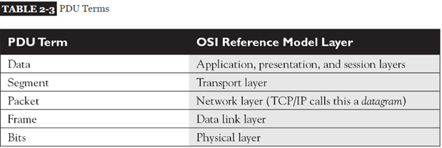
- As this information is passed from higher to lower layers, each layer adds information to the original data—typically a header and possibly a trailer. This process is called encapsulation
- Generically speaking, the term protocol data unit (PDU) is used to describe data and its overhead.
Going Down the Protocol Stack
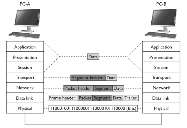
- The first thing that occurs on PC-A is that the user, sitting in front of the computer, creates some type of information, called data, and then sends it to another location (PC-B)
- This includes the actual user input (application layer), as well as any formatting information (presentation layer)
- The application (or operating system), at the session layer, then determines whether or not the data’s intended destination is local to this computer (possibly a disk drive) or a remote location.
- The session layer determines that this location is remote and has the transport layer deliver the information. A telnet connection uses TCP/IP and reliable connections (TCP) at the transport layer, which encapsulates the data from the higher layers into a segment. With TCP, as you will see in only a header is added. The segment contains such information as the source and destination port numbers. ” the source port is a number above 1023 that is currently not being used by PC-A. The destination port number is the well-known port number (23) that the destination will understand and forward to the telnet application.
- The transport layer passes the segment down to the network layer, which encapsulates the segment into a packet. The packet adds only a header, which contains layer 3 logical addressing information (source and destination address), as well as other information, such as the upper-layer protocol that created this information. In this example, TCP created this information, so this fact is noted in the packet header, and PC-A places its IP address as the source address in the packet and PC-B’s IP address as the destination. This helps the destination, at the network layer, determine whether the packet is for itself and which upper-layer process should handle the encapsulated segment. In the TCP/IP protocol stack, the terms packet and datagram are used interchangeably to describe this PDU. As you will see in many protocols are within the TCP/IP protocol stack—ARP, TCP, UDP, ICMP, OSPF, EIGRP, and many others.
- The network layer then passes the packet down to the data link layer. The data link layer encapsulates the packet into a frame by adding both a header and a trailer. This example uses Ethernet as the data link layer medium, discussed in more depth in other post. The important components placed in the Ethernet frame header are the source and destination MAC addresses, as well as a field checksum sequence (FCS) value so that the destination can determine whether the frame is valid or corrupted when it is received. In this example, PC-A places its MAC address in the frame in the source field and PC-B’s MAC address in the destination field.
- The data link layer frame is then passed down to the physical layer. At this point, remember that the concept of “PDUs” is a human concept that we have placed on the data to make it more readable to us, as well as to help deliver the information to the destination. However, from a computer’s perspective, the data is just a bunch of binary values, 1s and 0s, called bits. The physical layer converts these bits into a physical property based on the cable or connection type. In this example, the cable is a copper cable, so the physical layer will convert the bits into voltages: one voltage level for a bit value of 1 and a different voltage level for a 0.
Going Up the Protocol Stack
For sake of simplicity, assume PC-A and PC-B are on the same piece of copper. Once the destination receives the physical layer signals, the physical layer translates the voltage levels back to their binary representation and passes these bit values up to the data link layer.
The data link layer takes the bit values and reassembles them into the original data link frame (Ethernet). The NIC, at the MAC layer, examines the FCS to make sure the frame is valid and examines the destination MAC address to ensure that the Ethernet frame is meant for itself. If the destination MAC address doesn’t match its own MAC address, or it is not a multicast or broadcast address, the NIC drops the frame. Otherwise, the NIC processes the frame. In this case, the NIC sees that the encapsulated packet is a TCP/IP packet, so it strips off (de-encapsulates) the Ethernet frame information and passes the packet up to the TCP/IP protocol stack at the network layer.
The network layer then examines the logical destination address in the packet header. If the destination logical address doesn’t match its own address or is not a multicast or broadcast address, the network layer drops the packet. If the logical address matches, then the destination examines the protocol information in the packet header to determine which protocol should handle the packet. In this example, the logical address matches and the protocol is defined as TCP. Therefore, the network layer strips off the packet information and passes the encapsulated segment up to the TCP protocol at the transport layer.
Upon receiving the segment, the transport layer protocol can perform many functions, depending on whether this is a reliable or unreliable connection. This discussion focuses on the multiplexing function of the transport layer. In this instance, the transport layer examines the destination port number in the segment header. In our example, the user from PC-A was using telnet to transmit information to PC-B, so the destination port number is 23. The transport layer examines this port number and realizes that the encapsulated data needs to be forwarded to the telnet application. If PC-B doesn’t support telnet, the transport layer drops the segment. If it does, the transport layer strips off the segment information and passes the encapsulated data to the telnet application. If this is a new connection, a new telnet process is started up by the operating system.
Note that a logical communication takes place between two layers of two devices. For instance, a logical communication occurs at the transport layer between PC-A and PC-B, and this is also true at the network and data link layers.
In this example, PC-A wants to send data to PC-B. Notice that each device needs to process information at specific layers
For instance, once PC-A places its information on the wire, the switch connected to PC-A needs to process this information

Layers and Communication
As you can see from the encapsulation and de-encapsulation process, many processes are occurring on both the source and destination computers to transmit and receive the information. This can become even more complicated if the source and destination are on different segments, separated by other networking devices, such as hubs, switches, and routers. Figure shows an example of this process.
Switches function at layer 2 of the OSI Reference Model. Whereas routers make path decisions based on destination layer 3 logical addresses, switches make path decisions based on layer 2 destination MAC addresses found in frames. Therefore, the switch’s physical layer will have to convert the physical layer signal into bits and pass these bits up to the data link layer, where they are reassembled into a frame. The switch examines the destination MAC address and makes a switching decision, finding the port the frame needs to exit. It then passes the frame down to the physical layer, where the bits of the frame are converted into physical layer signals.
The next device the physical layers encounter is a router routers function at layer 3 of the OSI Reference Model. The router first converts the physical layer signals into bits at the physical layer. The bits are passed up to the data link layer and reassembled into a frame. The router then examines the destination MAC address in the frame. If the MAC address doesn’t match its own MAC address, the router drops the frame. If the MAC address matches, the router strips off the data link layer frame and passes the packet up to the network layer.
At the network layer, one of the functions of the router is to route packets to destinations. To accomplish this, the router examines the destination logical address in the packet and extracts a network number from this address. The router then compares the network number to entries in its routing table. If the router doesn’t find a match, it drops the packet; if it does find a match, it forwards the packet out the destination interface (the local interface designated by the router’s routing table).
To accomplish the packet forwarding, the router passes the packet down to the data link layer, which encapsulates the packet into the correct data link layer frame format. If this were an Ethernet frame, for this example, the source MAC address would be that of the router and the destination would be PC-B. At the data link layer, the frame is then passed down to the physical layer, where the bits are converted into physical layer signals.
When sending traffic between two devices on different segments, the source device has a layer 2 frame with its own MAC address as the source and the default gateway’s (router) MAC address as the destination; however, in the layer 3 packet, the source layer 3 address is the source device and the destination layer 3 address is not the default gateway, but the actual destination the source is trying to reach. Remember that layer 2 addresses are used to communicate with devices on the same physical or logical layer 2 segment/network, and layer 3 addresses are used to communicate with devices across the network (multiple segments). Another way to remember this is that MAC addresses can change from link to link, but layer 3 logical addresses, by default, cannot.
The next device that receives these physical layer signals is the hub Basically, a hub is a multiport repeater: It repeats any physical layer signal it receives. Therefore, a signal received on one interface of a hub is repeated on all of its other interfaces. These signals are then received by PC-B, which passes this information up the protocol stack
Ethernet Frame Format :
- When transmitting data over Ethernet, the Ethernet frame is primarily responsible for the correct rule making and successful transmission of data packets. Essentially, data sent over Ethernet is carried by the frame. An Ethernet frame is between 64 bytes and 1,518 bytes big, depending on the size of the data to be transported.
- The frame was first defined in the original Ethernet DEC-Intel-Xerox (DIX) standard, and was later redefined and modified in the IEEE 802.3 standard. The changes between the two standards were mostly cosmetic, except for the type or length field.
- The DIX standard defined a type field in the frame. The first 802.3 standard (published in 1985) specified this field as a length field, with a mechanism that allowed both versions of frames to coexist on the same Ethernet system
The standard recommends that new implementations support the most recent frame definition, called an envelope frame, which has a maximum size of 2,000 bytes. The two other sizes are basic frames, with a maximum size of 1,518 bytes, and Q-tagged frames with a maximum of 1,522 bytes
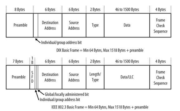
- Because the DIX and IEEE basic frames both have a maximum size of 1,518 bytes and are identical in terms of the number and length of fields, Ethernet interfaces can send either DIX or IEEE basic frames. The only difference in these frames is in the contents of the fields and the subsequent interpretation of those contents by the network interface software.
ETHERNET FRAME FORMATS
The explanation for the many types of Ethernet Frame Formats currently on the marketplace lies in Ethernet’s history. In 1972, work on the original version of Ethernet, Ethernet Version 1, began at the Xerox Palo Alto Research Center. Version 1 Ethernet was released in 1980 by a consortium of companies comprising DEC, Intel, and Xerox. In the same year, the IEEE meetings on Ethernet began. In 1982, the DIX (DEC/Intel/Xerox) consortium released Version II Ethernet and since then it has almost completely replaced Version I in the marketplace. In 1983 Novell NetWare ’86 was released, with a proprietary frame format based on a preliminary release of the 802.3 spec. Two years later, when the final version of the 802.3 spec was released, it had been modified to include the 802.2 LLC Header, making NetWare’s proprietary format incompatible. Finally, the 802.3 SNAP format was created to address backwards compatibility issues between Version 2 and 802.3 Ethernet.
There are several types of Ethernet frames:
- Ethernet II frame, or Ethernet Version 2, or DIX frame is the most common type in use today, as it is often used directly by the Internet Protocol.
- Novell raw IEEE 802.3 non-standard variation frame
- IEEE 802.2 Logical Link Control (LLC) frame
- IEEE 802.2 Subnetwork Access Protocol (SNAP) frame
In addition, all four Ethernet frame types may optionally contain an IEEE 802.1Q tag to identify what VLAN it belongs to and its priority (quality of service). This encapsulation is defined in the IEEE 802.3ac specification and increases the maximum frame by 4 octets.
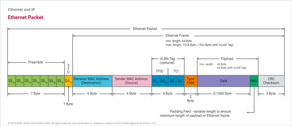
There is a size limitation for Ethernet Frame. The total size of the ethernet frame must be between 64 bytes and 1,518 bytes (not including the preamble)
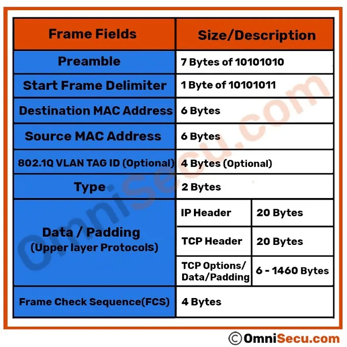
the minimum size of an Ethernet Frame must be 64 bytes (6+6+2+46+4) and maximum size of an Ethernet Frame 1,518 bytes (6+6+2+1500+4).
THE ETHERNET II FRAME FORMAT

- PREAMBLE
The frame begins with the 64-bit preamble field, which was originally incorporated to allow 10 Mb/s Ethernet interfaces to synchronize with the incoming data stream before the fields relevant to
A sequence of 56 bits (7 bytes) having alternating 1 and 0 values (10101010101010101010101010101010101010101010101010101010) that are used for synchronization.
- It is a 7 byte field that contains a pattern of alternating 0’s and 1’s.
- It alerts the stations that a frame is going to start.
- It also enables the sender and receiver to establish bit synchronization.
Why Need of PREAMBLE Bits ?
- The preamble was initially provided to allow for the loss of a few bits due to signal start-up delays as the signal propagates through a cabling system. Like the heat shield of a spacecraft, which protects the spacecraft from burning up during reentry, the preamble was originally developed as a shield to protect the bits in the rest of the frame when operating at 10 Mb/s.
- The original 10 Mb/s cabling systems could include long stretches of coaxial cables, joined by signal repeaters. The preamble ensures that the entire path has enough time to start up, so that signals are received reliably for the rest of the frame.
- While there are differences in how the two standards formally defined the preamble bits, there is no practical difference between the DIX and IEEE preambles. The pattern of bits being sent is identical
Start Frame Delimiter (SFD)-
- It is a 1 byte field which is always set to 10101011.
- The last two bits “11” indicate the end of Start Frame Delimiter and marks the beginning of the frame
- SFD indicates that upcoming bits are starting the frame, which is the destination address. Sometimes SFD is considered part of PRE, this is the reason Preamble is described as 8 Bytes in many places. The SFD warns station or stations that this is the last chance for synchronization.
NOTES
- The above two fields are added by the physical layer and represents the physical layer header.
- Sometimes, Start Frame Delimiter (SFD) is considered to be a part of Preamble.
- That is why, at many places, Preamble field length is described as 8 bytes.
DESTINATION ADDRESS
The destination address field follows the preamble. Each Ethernet interface is assigned a unique 48-bit address, called the interface’s physical or hardware address. The destination address field contains either the 48-bit Ethernet address that corresponds to the address of the interface in the station that is the destination of the frame, a 48-bit multicast address, or the broadcast address
- The Destination Address specifies to which adapter the data frame is being sent. A Destination Address of all ones specifies a Broadcast Message that is read in by all receiving Ethernet adapters.
- The first three bytes of the Destination Address are assigned by the IEEE to the vendor of the adapter and are specific to the vendor.
- The Destination Address format is identical in all implementations of Ethernet.
The first bit of the destination address, as sent onto the network medium, is used to distinguish physical addresses from multicast addresses. If the first bit is zero, then the address is the physical address of an interface, which is also known as a unicast address, because a frame sent to this address only goes to one destination.00 If all 48 bits are ones, this indicates the broadcast, or all-stations, address.
IEEE standard
The IEEE 802.3 version of the frame adds significance to the second bit of the destination address, which is used to distinguish between locally and globally administered addresses. A globally administered address is a physical address assigned to the interface by the manufacturer, which is indicated by setting the second bit to zero. (DIX Ethernet addresses are always globally administered.) If the address of the Ethernet interface is administered locally for some reason, then the second bit is supposed to be set to a value of one. In the case of a broadcast address, the second bit and all other bits are ones in both the DIX and IEEE standards.
Understanding physical addresses
In Ethernet, the 48-bit physical address is written as 12 hexadecimal digits with the digits paired in groups of two, representing an octet (8 bits) of information
This means that an Ethernet address that is written as the hexadecimal string F0-2E-15-6C-77-9B is equivalent to the following sequence of bits, sent over the Ethernet channel from left to right:0000 1111 0111 0100 1010 1000 0011 0110 1110 1110 1101 1001
Therefore, the 48-bit destination address that begins with the hexadecimal value 0xF0 is a unicast address, because the first bit sent on the channel is a zero.
The Source Address
The next six bytes of an Ethernet frame make up the Source Address. The Source Address specifies from which adapter the message originated. Like the Destination Address, the first three bytes specify the vendor of the card.
The Source Address format is identical in all implementations of Ethernet.
The source address is not interpreted in any way by the Ethernet MAC protocol, although it must always be the unicast address of the device sending the frame
Ethernet equipment acquires an organizationally unique identifier (OUI), which is a unique 24-bit identifier assigned by the IEEE. The OUI forms the first half of the physical address of any Ethernet interface that the vendor manufactures. As each interface is manufactured, the vendor also assigns a unique address to the interface using the second 24 bits of the 48-bit address space, and that, combined with the OUI, creates the 48-bit address.
Offset 12-13: The Ethertype
- Following the Source Address is a 2 byte field called the Ethertype.
An interesting question arises when one considers the 802.3 and Version II frame formats: Both formats specify a 2 byte field following the source address (an Ethertype in Version II, and a Length field in 802.3) — So how does a driver know which format it is seeing, if it is configured to support both Ethernet frames?
The answer is actually quite simple. All Ethertypes have a value greater than 05DC hex, or 1500 decimal. Since the maximum frame size in Ethernet is 1518 bytes, there is no point in overlapping between Ethertypes and lengths. If the field that follows the Source Address is greater than O5DC hex, the frame is a Version II, otherwise it is something else (either 802.3, 802.3 SNAP or Novell Proprietary)
| Network Layer Protocol | Hexadecimal Code |
|---|---|
| IPv4 | 0x0800 |
| IPv6 | 0x86DD |
| IEEE 802.1Q (VLAN Tagged Frame) | 0x8100 |
| IEEE 802.1X (EAP over LAN) | 0x888E |
| ARP (Address Resolution Protocol) | 0x0806 |
| RARP (Reverse Address Resolution Protocol) | 0x8035 |
| Simple Network Management Protocol (SNMP) | 0x814C |
Maximum Length of Data Field
- The maximum amount of data that can be sent in a Ethernet frame is 1500 bytes.
- This is to avoid the monopoly of any single station.
- If Ethernet allows the frames of big sizes, then other stations may not get the fair chance to send their data
FCS FIELD
- The last field in both the DIX and IEEE frames is the frame check sequence (FCS) field, also called the cyclic redundancy check (CRC).This 32-bit field contains a value that is used to check the integrity of the various bits in the frame fields (not including the preamble/SFD).
- This value is computed using the CRC, a polynomial that is calculated using the contents of the destination, source, type (or length), and data fields
- As the frame is generated by the transmitting station, the CRC value is simultaneously being calculated. The 32 bits of the CRC value that are the result of this calculation are placed in the FCS field as the frame is sent.
- The CRC is calculated again by the interface in the receiving station as the frame is read in. The result of this second calculation is compared with the value sent in the FCS field by the originating station. If the two values are identical, then the receiving station is provided with a high level of assurance that no errors have occurred during transmission over the Ethernet channel. If the values are not identical, then the interface can discard the frame and increment the frame error counter.
- END OF FRAME DETECTION
The presence of a signal on the Ethernet channel is known as carrier
- The transmitting interface stops sending data after the last bit of a frame is transmitted, which causes the Ethernet channel to become idle.
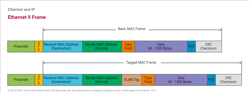
V-LAN Tagged Frame
The IEEE specifications define different formats for Ethernet frames. The automotive industry typically uses the Ethernet II frame, which can also contain information for VLAN as an extension. For this reason, a distinction is made between the basic MAC frame (without VLAN) and the tagged MAC frame (including VLAN).
A VLAN tag consists of a protocol identifier (TPID) and control information (TCI). While the TPID contains the value of the original type field, the TCI consists of a Priority (PCP), a Drop Eligible or Canonical Form Indicator (DEI or CFI), and an Identifier (VID). Identifier and Priority are mainly used in the automotive industry. The Identifier distinguishes the respective virtual network for the different application areas. The Priority allows optimization of run-times through switches so that important information is forwarded preferentially.
THE IEEE 802.3 SNAP FRAME FORMAT
While the original 802.3 specification worked well, the IEEE realized that some upper layer protocols required an Ether type to work properly. For example, TCP/IP uses the Ether type to differentiate between ARP packets and normal IP data frames. In order to provide this backwards compatibility with the Version II frame type, the 802.3 SNAP (Sub Network Access Protocol) format was created.
The SNAP Frame Format consists of a normal 802.3 Data Link Header followed by a normal 802.2 LLC Header and then a 5-byte SNAP field, followed by the normal user data and FCS.

Offset 0-5: The Destination Address
- The first six bytes of an Ethernet frame make up the Destination Address. The Destination Address specifies to which adapter the data frame is being sent. A Destination Address of all ones specifies a Broadcast Message that is read in by all receiving Ethernet adapters.
- The first three bytes of the Destination Address are assigned by the IEEE to the vendor of the adapter and are specific to the vendor.
- The Destination Address format is identical in all implementations of Ethernet.
Offset 6-11: The Source Address
- The next six bytes of an Ethernet frame make up the Source Address. The Source Address specifies from which adapter the message originated. Like the Destination Address, the first three bytes specify the vendor of the card.
- The Source Address format is identical in all implementations of Ethernet.
Offset 12-13: Length
- Bytes 13 and 14 of an Ethernet frame contain the length of the data in the frame, not including the preamble, 32 bit CRC, DLC addresses, or the Length field itself. An Ethernet frame can be no shorter than 64 bytes total length and no longer than 1518 bytes total length.
Following the Datalink Header is the Logical Link Control (LLC) Header, which is described in the IEEE 802.2 Specification. The purpose of the LLC header is to provide a “hole in the ceiling” of the Datalink Layer. By specifying into which memory buffer the adapter places the data frame, the LLC header allows the upper layers to know where to find the data.
Offset 15: The Destination Service Access Point (DSAP)
- The Destination Service Access Point or DSAP, is a 1 byte field that simply acts as a pointer to a memory buffer in the receiving station. It tells the receiving network interface card in which buffer to put this information. This functionality is crucial in situations where users are running multiple protocol stacks, etc…
Offset 16: The Source Service Access Point (SSAP)
- The Source Service Access Point or SSAP is analogous to the DSAP and specifies the Source of the sending process.
Offset 17: The Control Byte
- Following the SAPs is a one byte control field that specifies the type of LLC frame that this is.
The LLC header includes two eight-bit address fields, called service access points (SAPs) in OSI terminology; when both source and destination SAP are set to the value 0xAA, the LLC header is followed by a SNAP header. The SNAP header allows EtherType values to be used with all IEEE 802 protocols, as well as supporting private protocol ID spaces.
- Common SAP values include:
| o | hex ’04’ – IBM SNA (Systems Network Architecture) |
| o | hex ’06’ – IP (Internet Protocol) |
| o | hex ’12’ – LAN Printing |
| o | hex ‘AA’ – SNAP (Sub-Network Access Protocol) |
| o | hex ‘BC’ – Banyan |
| o | hex ‘C8’ – HPR (High Performance Routing) |
| o | hex ‘E0’ – Novell |
Offset 18-20: The Vendor Code
- The first 3 bytes of the SNAP header is the vendor code, generally the same as the first three bytes of the source address although it is sometimes set to zero.
Offset 21-22: The Local Code
- Following the Vendor Code is a 2 byte field that typically contains an Ether type for the frame. This is where the backwards compatibility with Version II Ethernet is implemented.
USER DATA AND THE FRAME CHECK SEQUENCE (FCS)

Data: 38-1492 Bytes
- Following the 802.2 header are 38 to 1492 bytes of data, generally consisting of upper layer headers such as TCP/IP or IPX and then the actual user data.
FCS: Last 4 Bytes
- The last 4 bytes that the adapter reads in are the Frame Check Sequence or CRC. When the voltage on the wire returns to zero, the adapter checks the last 4 bytes it received against a checksum that it generates via a complex polynomial. If the calculated checksum does not match the checksum on the frame, the frame is discarded and never reaches the memory buffers in the station.
- When using a SNAP header, the 802.2 LLC header is always the same:
DSAP (1 byte) = hex ‘AA’
SSAP (1 byte) = hex ‘AA’
Control (1 byte) = hex ’03’
- The SNAP header is 5 bytes and is included in the frame immediately following the 802.2 LLC header.
The first 3 bytes of the SNAP header are referred to as the Organization Unique Identifier (OUI), or simply the Organization ID. This indicates the company to which the embedded non-compliant protocol belongs.
Common OUI values include:
’00-02-55′ – IBM Corporation (along with many other OUIs)
’00-00-0C’ – Cisco Systems (along with many other OUIs)
’00-80-C2′ – IEEE 802.1 Committee
Note: Most of the time, this field is set to ’00-00-00′.
The last 2 bytes of the SNAP header include the EtherType (sometimes called the protocol ID), which indicates the embedded non-compliant protocol. These are the same as the EtherTypes included in the Ethernet Version 2 frame format.
References:
https://www.ionos.com/digitalguide/server/know-how/ethernet-frame
