Introduction
Internet addresses allow any machine on the network to communicate with any other machine on the network.
TCP/IP provides facilities that make the computer system an Internet host, which can attach to a network and communicate with other Internet hosts
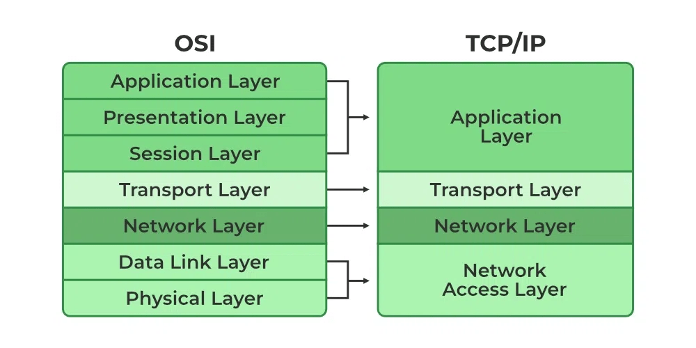
The TCP/IP protocol stack actually doesn’t define the components of the network access layer in the TCP/IP standards, but it uses the term to refer to layer 2 and layer 1 functions.
Whereas the OSI model has seven layers, the TCP/IP protocol stack has only four layers. Its application layer covers the application, presentation, and session layers of the OSI Reference Model, its Internet layer corresponds to the OSI model’s network layer to describe layer 3, and its network access layer includes both the data link and physical layers of the OSI model.
As the name implies, TCP/IP is a combination of two separate protocols: TCP(transmission control protocol) and IP (Internet protocol). The Internet Protocol standard dictates the logistics of packets sent out over networks; it tells packets where to go and how to get there. IP has a method that lets any computer on the Internet forward a packet to another computer that is one or more intervals closer to the packet’s recipient. You can think of it like workers in a line passing boulders from a quarry to a mining cart.
What is the Difference between TCP and IP?
TCP and IP are different protocols of Computer Networks. The basic difference between TCP (Transmission Control Protocol) and IP (Internet Protocol) is in the transmission of data. In simple words, IP finds the destination of the mail and TCP has the work to send and receive the mail. UDP is another protocol, which does not require IP to communicate with another computer. IP is required by only TCP. This is the basic difference between TCP and IP.
What are the different layers of TCP/IP?
There are four total layers of TCP/IP protocol, listed below with a brief description.
- Network Access Layer – This layer is concerned with building packets
- Internet Layer – This layer uses IP (Internet Protocol) to describe how packets are to be delivered. IP: IP stands for Internet Protocol and it is responsible for delivering packets from the source host to the destination host by looking at the IP addresses in the packet headers. IP has 2 versions: IPv4 and IPv6. IPv4 is the one that most websites are using currently. But IPv6 is growing as the number of IPv4 addresses is limited in number when compared to the number of users.
- Transport Layer – This layer utilizes UDP(User Datagram Protocol) and TCP(Transmission Control Protocol) to ensure the proper transmission of data.The TCP/IP transport layer protocols exchange data receipt acknowledgments and retransmit missing packets to ensure that packets arrive in order and without error. End-to-end communication is referred to as such. Transmission Control Protocol (TCP) and User Datagram Protocol are transport layer protocols at this level (UDP).TCP: Applications can interact with one another using TCP as though they were physically connected by a circuit. TCP transmits data in a way that resembles character-by-character transmission rather than separate packets. A starting point that establishes the connection, the whole transmission in byte order, and an ending point that closes the connection make up this transmission.UDP: The datagram delivery service is provided by UDP, the other transport layer protocol. Connections between receiving and sending hosts are not verified by UDP. Applications that transport little amounts of data use UDP rather than TCP because it eliminates the processes of establishing and validating connections.
- Application Layer – This layer deals with application network processes. These processes include FTP(File Transfer Protocol), HTTP(Hypertext Transfer Protocol), and SMTP(Simple Mail Transfer Protocol).
The IP protocol is mainly responsible for these functions:
- Connectionless data delivery: best-effort delivery with no data recovery capabilities
- Hierarchical logical addressing to provide for highly scalable internetworks
The Internet layer is primarily responsible for network addressing and routing of IP packets. IP protocols at the Internet layer include Address Resolution Protocol (ARP), Reverse Address Resolution Protocol (RARP), Internet Control Management Protocol (ICMP), Open Shortest Path First (OSPF)
Where the transport layer uses segments to transfer information between machines, the Internet layer uses datagrams. (Datagram is just another word for packet
The main function of the IP datagram is to carry protocol information for either Internet layer protocols (other TCP/IP layer 3 protocols) or encapsulated transport layer protocols (TCP and User Datagram Protocol, or UDP). To designate what protocol the IP datagram is carrying in the data field, the IP datagram carries the protocol’s number in the Protocol field.
some common IP protocols and their protocol numbers: ICMP (1), IPv6 (41), TCP (6), UDP (17), Enhanced Interior Gateway Routing Protocol (EIGRP) (88), and OSPF (89). Notice that routing occurs at the Internet layer
Frame Structure
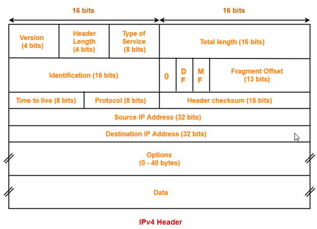
1) Version: The first header field is a 4-bit version indicator. In the case of IPv4, the value of its four bits is set to 0100 which indicates 4 in binary.
2) Internet Header Length: IHL is the 2nd field of an IPv4 header and it is of 4 bits in size. This header component is used to show how many 32-bit words are present in the header. As we know, IPv4 headers have a variable size so this is used to specify the size of the header to avoid any errors. This size can be between 20 bytes to 60 bytes.
- The initial 5 rows of the IP header are always used.
- So, minimum length of IP header = 5 x 4 bytes = 20 bytes.
- The size of the 6th row representing the Options field vary.
- The size of Options field can go up to 40 bytes.
- So, maximum length of IP header = 20 bytes + 40 bytes = 60 bytes.
Concept of Scaling Factor-
- Header length is a 4 bit field.
- So, the range of decimal values that can be represented is [0, 15].
- But the range of header length is [20, 60].
- So, to represent the header length, we use a scaling factor of 4.
In general,
| Header length = Header length field value x 4 bytes |
Examples-
- If header length field contains decimal value 5 (represented as 0101), then-
Header length = 5 x 4 = 20 bytes
- If header length field contains decimal value 10 (represented as 1010), then-
Header length = 10 x 4 = 40 bytes
- If header length field contains decimal value 15 (represented as 1111), then-
Header length = 15 x 4 = 60 bytes
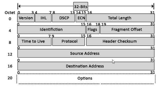
3) Type Of Service–
- Type of service is a 8 bit field that is used for Quality of Service (QoS).
- The datagram is marked for giving a certain treatment using this field.
- ToS is also called Differentiated Services Code Point or DSCP. This field is used to provide features related to the quality of service such as for data streaming or Voice over IP (VoIP) calls. It is used to specific how a datagram will be handled.
4) Total Length-
- Total length is a 16 bit field that contains the total length of the datagram (in bytes).
- Total Length: Size of this field is 16 bit and it is used to denote the size of the entire datagram. The minimum size of an IP datagram is 20 bytes and at the maximum, it can be 65,535 bytes. Practically, all hosts are required to be able to read 576-byte datagrams. If a datagram is too large for the hosts in the network, fragmentation is used which is handled in the host or packet switch.
5) Identification-
- Identification is a 16 bit field.
- It is used for the identification of the fragments of an original IP datagram.
When an IP datagram is fragmented,
- Each fragmented datagram is assigned the same identification number.
- This number is useful during the re assembly of fragmented datagrams.
- It helps to identify to which IP datagram, the fragmented datagram belongs to.
6) Flags: flag in an IPv4 header is a three-bit field that is used to control and identify fragments. The following can be their possible configuration:
- Bit 0: this is reserved and has to be set to zero
- Bit 1: DF or do not fragment
- Bit 2: MF or more fragments
DF Bit-
- DF bit stands for Do Not Fragment bit.
- Its value may be 0 or 1.
When DF bit is set to 0,
- It grants the permission to the intermediate devices to fragment the datagram if required.
When DF bit is set to 1,
- It indicates the intermediate devices not to fragment the IP datagram at any cost.
- If network requires the datagram to be fragmented to travel further but settings does not allow its fragmentation, then it is discarded.
- An error message is sent to the sender saying that the datagram has been discarded due to its settings.
7. MF Bit-
- MF bit stands for More Fragments bit.
- Its value may be 0 or 1.
When MF bit is set to 0,
- It indicates to the receiver that the current datagram is either the last fragment in the set or that it is the only fragment.
When MF bit is set to 1,
- It indicates to the receiver that the current datagram is a fragment of some larger datagram.
- More fragments are following.
- MF bit is set to 1 on all the fragments except the last one.
- Time to live (or TTL in short) is an 8-bit field to indicate the maximum time the datagram will be live in the internet system. The time here is measured in seconds and in case the value of TTL is zero, the datagram is erased. Every time a datagram is processed, it’s Time to live is decreased by one second. These are used so that datagrams that are not delivered are discarded automatically. TTL can be between 0 – 255.
- Time to live (TTL) is a 8 bit field.
- It indicates the maximum number of hops a datagram can take to reach the destination.
- The main purpose of TTL is to prevent the IP datagrams from looping around forever in a routing loop.
The value of TTL is decremented by 1 when-
- Datagram takes a hop to any intermediate device having network layer.
- Datagram takes a hop to the destination.
If the value of TTL becomes zero before reaching the destination, then datagram is discarded
It is important to note-
- Both intermediate devices having network layer and destination decrements the TTL value by 1.
- If the value of TTL is found to be zero at any intermediate device, then the datagram is discarded.
- So, at any intermediate device, the value of TTL must be greater than zero to proceed further.
- If the value of TTL becomes zero at the destination, then the datagram is accepted.
- So, at the destination, the value of TTL may be greater than or equal to zero.
8) Protocol: This is a filed in the IPv4 header reserved to denote which protocol is used in the later (data) portion of the datagram. For Example, number 6 is used to denote TCP and 17 is used to denote UDP protocol
· It tells the network layer at the destination host to which protocol the IP datagram belongs to.
· In other words, it tells the next level protocol to the network layer at the destination side.
· Protocol number of ICMP is 1, IGMP is 2, TCP is 6 and UDP is 17.
Why Protocol Number Is A Part Of IP Header?
Consider-
- An IP datagram is sent by the sender to the receiver.
- When datagram reaches at the router, it’s buffer is already full.
In such a case,
- Router does not discard the datagram directly.
- Before discarding, router checks the next level protocol number mentioned in its IP header.
- If the datagram belongs to TCP, then it tries to make room for the datagram in its buffer.
- It creates a room by eliminating one of the datagrams having lower priority.
- This is because it knows that TCP is a reliable protocol and if it discards the datagram, then it will be sent again by the sender.
- The order in which router eliminate the datagrams from its buffer is-
ICMP > IGMP > UDP > TCP
If protocol number would have been inside the datagram, then-
- Router could not look into it.
- This is because router has only three layers- physical layer, data link layer and network layer.
That is why, protocol number is made a part of IP header.
9) Header Checksum-
- Header checksum is a 16 bit field.
- It contains the checksum value of the entire header.
- The checksum value is used for error checking of the header.
At each hop,
- The header checksum is compared with the value contained in this field.
- If header checksum is found to be mismatched, then the datagram is discarded.
- Router updates the checksum field whenever it modifies the datagram header.
- · Source Address: It is a 32-bit address of the source of the IPv4 packet.
- · Destination Address: the destination address is also 32 bit in size and it contains the address of the receiver.
Options-
- Options is a field whose size vary from 0 bytes to 40 bytes.
- This field is used for several purposes such as-
- Record route
- Source routing
- Padding
1. Record Route-
- A record route option is used to record the IP Address of the routers through which the datagram passes on its way.
- When record route option is set in the options field, IP Address of the router gets recorded in the Options field.
| The maximum number of IPv4 router addresses that can be recorded in the Record Route option field of an IPv4 header is 9. |
Explanation-
- In IPv4, size of IP Addresses = 32 bits = 4 bytes.
- Maximum size of Options field = 40 bytes.
- So, it seems maximum number of IP Addresses that can be recorded = 40 / 4 = 10.
- But some space is required to indicate the type of option being used.
- Also, some space is to be left between the IP Addresses.
- So, the space of 4 bytes is left for this purpose.
- Therefore, the maximum number of IP addresses that can be recorded = 9.
Padding-
- Addition of dummy data to fill up unused space in the transmission unit and make it conform to the standard size is called as padding.
- Options field is used for padding.
Example-
- When header length is not a multiple of 4, extra zeroes are padded in the Options field.
- By doing so, header length becomes a multiple of 4.
- If header length = 30 bytes, 2 bytes of dummy data is added to the header.
- This makes header length = 32 bytes.
- Then, the value 32 / 4 = 8 is put in the header length field.
- In worst case, 3 bytes of dummy data might have to be padded to make the header length a multiple of 4.
