ARP (Address Resolution Protocol) is a network protocol used to find out the hardware (MAC) address of a device from an IP address. It is used when a device wants to communicate with some other device on a local network (for example on an Ethernet network that requires physical addresses to be known before sending packets). The sending device uses ARP to translate IP addresses to MAC addresses. The device sends an ARP request message containing the IP address of the receiving device. All devices on a local network segment see the message, but only the device that has that IP address responds with the ARP reply message containing its MAC address. The sending device now has enough information to send the packet to the receiving device.
Basically stated, you have the IP address you want to reach, but you need a physical (MAC) address to send the frame to the destination at layer 2. ARP resolves an IP address of a destination to the MAC address of the destination on the same data link layer medium, such as Ethernet. Remember that for two devices to talk to each other in Ethernet (as with most layer 2 technologies), the data link layer uses a physical address (MAC) to differentiate the machines on the segment. When Ethernet devices talk to each other at the data link layer, they need to know each other’s MAC addresses.
ARP uses a local broadcast (255.255.255.255) at layer 3 and FF:FF:FF:FF:FF:FF at layer 2 to discover neighboring devices.
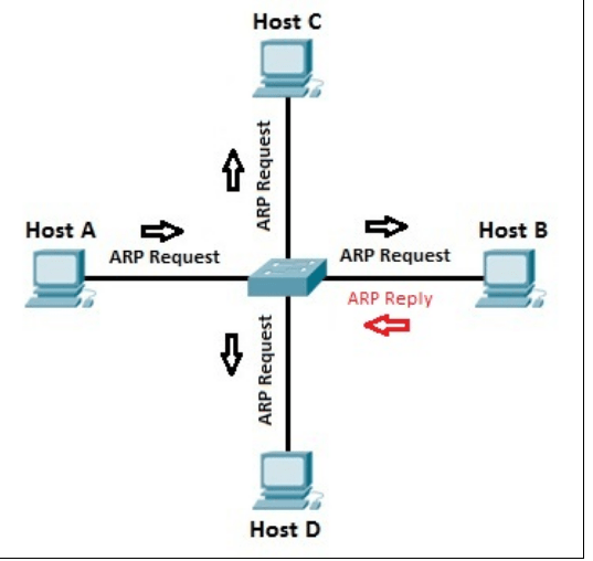
Single-Segment ARP Example
The top part of above figure shows an example of the use of ARP. In this example, PC-A wants to send information directly to PC-B. PC-A knows PC-B’s IP address (or has DNS resolve it to an IP address); however, it doesn’t know PC-B’s Ethernet MAC address. To resolve the IP address to a MAC address, PC-A generates an ARP request. In the ARP datagram, the source IP address is 10.1.1.1 and the destination is 255.255.255.255 (the local broadcast represents every device on the Ethernet segment). PC-A includes PC-B’s IP address in the data field of the ARP datagram. This is encapsulated into an Ethernet frame, with a source MAC address of 0000.0CCC.1111 (PC-A’s MAC address) and a destination MAC address of FF:FF:FF:FF:FF:FF (the local broadcast address) and is then placed on the Ethernet segment. Both PC-B and PC-C see this frame. Both devices’ NICs notice the data link layer broadcast address and assume that this frame is for them since the destination MAC address is a broadcast, so they strip off the Ethernet frame and pass the IP datagram with the ARP request up to the Internet layer. Again, there is a broadcast address in the destination IP address field, so both devices’ TCP/IP protocol stacks will examine the data payload. PC-B notices that this is an ARP request and that this is its own IP address in the query, and therefore responds directly back to PC-A with PC-B’s MAC address. PC-C, however, sees that this is not an ARP for its own MAC address and ignores the requested datagram
One important thing that both PC-B and PC-C will do is add PC-A’s MAC address to their local ARP tables. They do this so that if either device needs to communicate with PC-A, neither will have to perform the ARP request as PC-A had to. Entries in the ARP table will time out after a period of non-use of the MAC address.
Two-Segment ARP Example
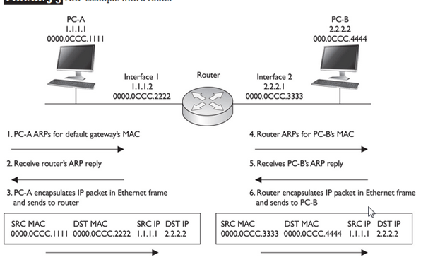
Figure below shows a more detailed example of the use of ARP. In this example, PC-A wants to connect to PC-B using IP. The source address is 1.1.1.1 (PC-A) and the destination is 2.2.2.2 (PC-B). Since the two devices are on different networks, a router is used to communicate between the networks. Therefore, if PC-A wants to send something to PC-B, it has to be sent via the intermediate router. However, this communication does not occur at the network layer using IP; instead, it occurs at the data link layer.
Assume that Ethernet is being used in this example. The first thing that PC-A will do is determine whether the destination, based on the layer 3 address, is local to this subnet or on another subnet. In this example, it’s a remote location, so PC-A will need to know the MAC address of the default gateway router. If the address isn’t already in its local ARP table, PC-A will generate an ARP request for the default gateway’s MAC address. (Note that one thing you must configure on PC-A, other than its own IP address and subnet mask, is the default gateway address, or you must acquire this information via DHCP.) This is shown in step 1 of Figure. In step 2, the router responds with the MAC address of its Ethernet interface connected to PC-A. In step 3, PC-A creates an IP packet with the source and destination IP addresses (the source is 1.1.1.1 and the destination is 2.2.2.2, PC-B) and encapsulates this in an Ethernet frame, with the source MAC address of PC-A and the destination MAC address of the router. PC-A then sends the Ethernet frame to the router.
When the router receives the Ethernet frame, the router compares the frame to the MAC address on its Ethernet interface, which it matches. The router strips off the Ethernet frame and makes a routing decision based on the destination address of 2.2.2.2. In this case, the network is directly connected to the router’s second interface, which also happens to be Ethernet. In step 4, if the router doesn’t have PC-B’s MAC address in its local ARP table, the router ARPs for the MAC address of PC-B (2.2.2.2) and receives the response in step 5. The router then encapsulates the original IP packet in a new Ethernet frame in step 6, placing its second interface’s MAC address, which is sourcing the frame, in the source MAC address field and PC-B’s MAC address in the destination field. When PC-B receives this, it knows the frame is for itself (matching destination MAC address) and that PC-A originated the IP packet that’s encapsulated based on the source IP address in the IP header at layer 3.
Note that in this example, the original IP addressing in the packet was not altered by the router, but two Ethernet frames are used to get the IP packet to the destination. Also, each device will keep the MAC addresses in a local ARP table, so the next time PC-A needs to send something to PC-B, the devices will not have to ARP other intermediate devices again.
ARP is used to determine the layer 2 address to use to communicate to a device in the same broadcast domain. Be familiar with which device talks to which other device at both layer 2 and layer 3. With a router between the source and destination, the source at layer 2 uses its own MAC address as the source but uses the default gateway MAC address as the destination. Note that the IP addresses used at layer 3 are not changed by the router
Traditional ARP
- Address Resolution Protocol (ARP) is the process by which a known L3 address is mapped to an unknown L2 address . The purpose for creating such a mapping is so a packet’s L2 header can be properly populated to deliver a packet to the next NIC in the path between two end points.
- If a host is speaking to another host on the same IP network, the target for the ARP request is the other host’s IP address. . If a host is speaking to another host on a different IP network, the target for the ARP request will be the Default Gateway’s IP address..
- In the same way, if a Router is delivering a packet to the destination host, the Router’s ARP target will be the Host’s IP address. If a Router is delivering a packet to the next Router in the path to the host, the ARP target will be the other Router’s Interface IP address – as indicated by the relative entry in the Routing table.
ARP Process
The Address Resolution itself is a two step process – a request and a response.
It starts with the initiator sending an ARP Request as a broadcast frame to the entire network. This request must be a broadcast, because at this point the initiator does not know the target’s MAC address, and is therefore unable to send a unicast frame to the target.
Since it was a broadcast, all nodes on the network will receive the ARP Request. All nodes will take a look at the content of the ARP request to determine whether they are the intended target. The nodes which are not the intended target will silently discard the packet.
The node which is the target of the ARP Request will then send an ARP Response back to the original sender. Since the target knows who sent the initial ARP Request, it is able to send the ARP Response unicast, directly back to the initiator.
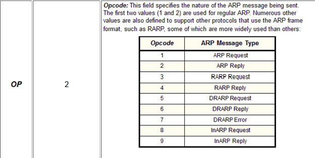
ARP Frame Format and types
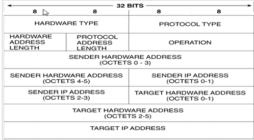
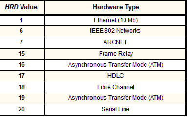
Hardware type
Each data link layer protocol is assigned a number used in this field. For Ethernet it is 1.
Protocol type
| PRO | 2 | Protocol Type: This field is the complement of the Hardware Type field, specifying the type of layer three addresses used in the message. For IPv4 addresses, this value is 2048 (0800 hex), which corresponds to the EtherType code for the Internet Protocol |
| HLN | 1 | Hardware Address Length: Specifies how long hardware addresses are in this message. For Ethernet or other networks using IEEE 802 MAC addresses, the value is 6. |
Length in bytes of a hardware address. Ethernet addresses are 6 bytes long.
Protocol length
Length in bytes of a logical address. IPv4 addresses are 4 bytes long.
| PLN | 1 | Protocol Address Length: Again, the complement of the preceding field; specifies how long protocol (layer three) addresses are in this message. For IP(v4) addresses this value is of course 4. |
Sender hardware address
Hardware address of the sender.
Sender Protocol Address: The IP address of the device sending this message.
Target hardware address
Hardware address of the intended receiver. This field is zero on request.
Target protocol address
Protocol address of the intended receiver.
ARP Function explained
ARP is used in four cases when two hosts are communicating:
1.When two hosts are on the same network and one desires to send a packet to the other
2.When two hosts are on the different networks and must use a gateway or router to reach the other host
3.When a router needs to forward a packet for one host through another router
4.When a router needs to forward a packet from one host to the destination host on the same network
- The assumption with ARP is that the device being ARPed is on the same segment
The following are four different cases in which the services of ARP can be used
- The sender is a host and wants to send a packet to another host on the same network. In this case, the logical address that must be mapped to a physical address is the destination IP address in the datagram header.
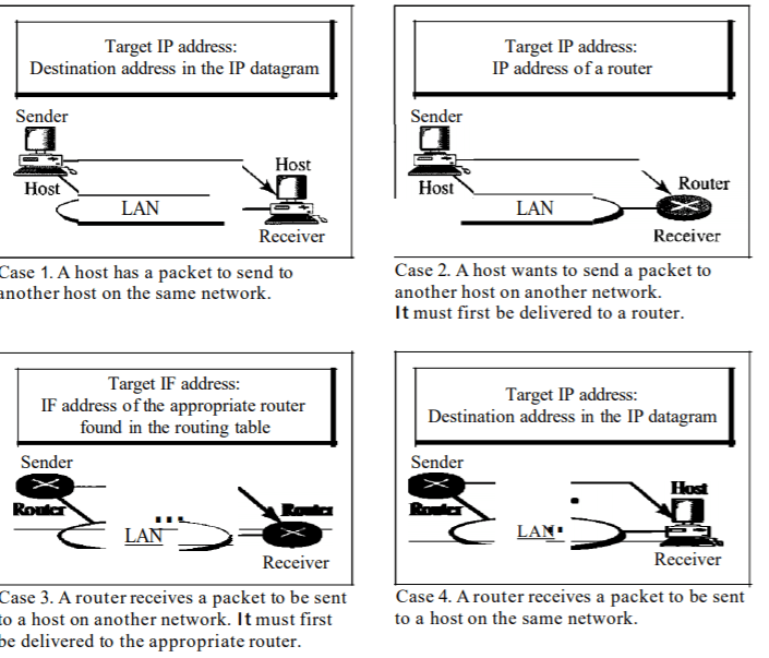
The sender is a host and wants to send a packet to another host on another network.
In this case, the host looks at its routing table and finds the IP address of the next
hop (router) for this destination. Ifit does not have a routing table, it looks for the
IP address of the default router. The IP address of the router becomes the logical
address that must be mapped to a physical address.
- The sender is a router that has received a datagram destined for a host on another network. It checks its routing table and finds the IP address of the next router. The IP address of the next router becomes the logical address that must be mapped to a physical address.
- The sender is a router that has received a datagram destined for a host on the same network. The destination IP address of the datagram becomes the logical address that must be mapped to a physical address.
