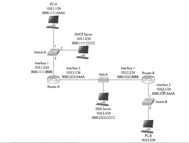
10.0.1.0/24 PC-A, Switch-A, and Router-A
10.0.2.0/24 Router-A, Hub-A, and Router-B
10.0.3.0/24 Router-B, Switch-B, and PC-B
Goal :
How PC-A acquires its IP addressing information using DHCP, how DNS works to resolve names, how PC-A and PC-B use TCP to perform telnet, how the three-way handshake occurs, how the switches switch frames, and how the routers route the packets. In this example, assume that the routers have static routes defined to reach the IP destinations and that the two switches have just booted up and haven’t learned any MAC addresses
PC-A Acquires Addressing Information
1. PC-A creates an Ethernet frame with an encapsulated DHCP Discover packet. The source MAC address in the frame is PC-A’s 0000.1111.AAAA, and the destination is a broadcast of FFFF.FFFF.FFFF.
2. When Switch-A receives the frame, it performs its learning process, adding 0000.1111.AAAA and port 1 to the CAM table. Since it is a broadcast, the switch floods the frame out ports 2 and 3.
3. Off port 3, when the router receives the frame, it processes it at layer 2, since the destination MAC address is a broadcast; but then it drops the frame at layer 3, since it isn’t a DHCP server.
4. Off port 2, when the DHCP server receives the frame, it processes it at layer 2, since it is a local broadcast, and forwards it up to layer 3.
- Assuming the DHCP server has a free address in its pool, the DHCP server responds with a DHCP OFFER message with IP addressing information: IP address of 10.0.1.1/24, DNS server address of 10.0.2.3, and a default gateway of 10.0.1.2. This is encapsulated in an Ethernet frame with a source MAC address of the server’s 0000.1111.CCCC and a destination MAC address of PC-A, 0000.1111.AAAA.
- When Switch-A receives the OFFER message, it does its learning function, adding 0000.1111.CCCC and port 2 to the CAM table. It then does its forwarding function, comparing the destination MAC address of 0000.1111 .AAAA to the CAM table, and sees that this is associated with port 1; so the switch forwards the frame out that port.
- PC-A receives the frame. The NIC compares its MAC address to the destination MAC address and sees a match, so it passes the IP packet up to layer 3, where the PC accepts the OFFER by sending a DHCP REQUEST message directly to the DHCP server: Switch-A switches the frame directly between these MAC addresses. PC-A also incorporates the IP addressing information into its NIC configuration.
- The DHCP server responds with a DHCP ACK message directly to PC-A, which the switch again directly switches to port 1.
Now that PC-A has IP addressing information, it can begin communicating, via TCP/IP, to other IP-enabled devices
Note : I have not gone through IP Renewal Process and DHCP Discover Process Packet Format.
PC-A Opens Up a Session to PC-B
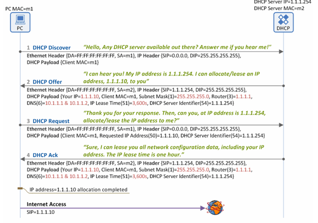
- PC-A Resolving PC-B’s Name Assume that PC-A doesn’t know the IP address of PC-B, but it does know its name. So from the Windows command prompt, the user on PC-A types the following:
C:\> telnet PC-B
- PC-A creates a DNS query for the name PC-B and sends this to the DNS server. Notice that since the DNS server is in a different subnet, the frame must be forwarded to the router first; therefore, the destination MAC address needed is Router-A’s MAC address.
- Since this is not originally known, PC-A will have to ARP for the MAC address associated with 10.0.1.2, the default gateway
- The source MAC address in the ARP is PC-A’s, and the destination MAC address is a broadcast, which Switch-A will flood. Router-A will respond to the ARP with the correct IP addressing information. (The router will also add PC-A’s IP and MAC addresses to its local ARP table.) In the Ethernet frame, the source MAC address will be the router’s destination MAC address, PC-B. The switch will perform its learning function, adding 0000.1111.BBBB (the router’s MAC address) to the CAM table.
- When PC-A receives the ARP reply, it can build the DNS query and forward it to the switch.

- Switch-A forwards the frame out port 3 directly to the router. Router-A, upon receiving the frame, examines the destination MAC address and sees that it matches the local interface’s MAC address. Router-A strips off the Ethernet frame and passes it up the TCP/IP stack. Since the destination IP address doesn’t match its own interface 1 address, the router examines its local routing table and notices that it is directly connected to subnet 10.0.2.0/24 on interface 2.
- Router-A knows that to get the frame to 10.0.2.3, the router will have to know the corresponding MAC address of the DNS server. If the router doesn’t have it in its local ARP table, the router will have to ARP for it
- The DNS server will add Router-A to its local ARP table and send an ARP reply to Router-A containing the DNS server’s MAC address.
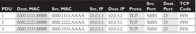
- Router-A can now forward the DNS query to the DNS server, using the information in PDU 2 in Table 9-1. Notice that the only thing that has changed from PDU 1 to PDU 2 is the Ethernet frame header information—the original IP packet and encapsulated UDP segment are still the same.
- When the DNS server receives the Ethernet frame, the NIC sees a match in the destination MAC address, strips off the Ethernet header, and forwards the IP packet up the protocol stack. The Internet layer compares the destination IP address with the server’s address, sees a match, sees that the protocol is UDP, and passes this up to the transport layer.
- The transport layer sees a destination port number of 53 and knows that the DNS application on the server should process the DNS query. The server looks up the name and then sends back an appropriate DNS reply, with an IP address of 10.0.3.2 for the PC-B lookup.
- notice that the source and destination UDP port numbers are reversed from the original DNS query. The source port number is the number the source uses, which is 53 in this case since the connection was directed to this port. The destination port number is 50,000, which PC-A is listening on for the returning UDP DNS reply.
- When Router-A receives the frame, it does its MAC comparison, strips off the Ethernet frame, does its route lookup, determines that the destination is directly off interface 1, examines the ARP table and sees the MAC address, and then re-encapsulates the DNS reply in a new Ethernet frame with a source MAC address of 0000.1111.BBBB and a destination MAC address of 0000.1111.AAAA
- The switch intelligently forwards the frame out of port 1. PC-A receives the frame, passes it up to layer 3, passes it up to layer 4, and sees the destination port of 50,000. PC-A compares this to its local connection table and knows that this is the DNS reply it’s waiting for, so it now knows the IP address of PC-B.
PC-A Sending a TCP SYN to PC-B
- Now that PC-A knows the IP address of PC-B, the telnet application can proceed with the actual telnet. Telnet uses TCP at the transport layer, so the three-way handshake must take place first. The first step is for PC-A to send a TCP segment with the SYN code (commonly called a flag) set. It uses a dynamic port above 49,151 and a destination, the well-known port of 23 for telnet.
- When the router receives this and processes the information, at layer 3 the router notices that the destination IP address is not its own; so the router does a lookup in its routing table and sees that the next hop at layer 3 is Router-B.
- If Router-A doesn’t know the IP-to-MAC address mapping of Router-B, it will ARP for it. Router-A then re-encapsulates the IP packet in a new Ethernet frame, shown in PDU 2 in Table 9-2: the IP and TCP headers remain the same, but a new frame header was generated to get its information across the 10.0.2.0/24 subnet.
- When Router-B receives the frame, it notices that the IP address doesn’t match its own, so Router-B looks in its routing table to see where the packet should be forwarded.
- If Router-B doesn’t know the IP-to-MAC address mapping for PC-B, Router-B will ARP for it. During the ARP request process, Switch-B will learn about Router-B’s MAC address and add it and port 1 to its CAM table (if it hasn’t already done this). Likewise, Switch-B will learn PC-B’s MAC address during the ARP reply process, if it doesn’t know it already. Router-B then encapsulates the IP packet in a new frame to get the data to PC-B. The Ethernet frame header, IP packet header, and TCP segment header are shown in PDU 3 of Table 9-2.
PC-B Sending a TCP SYN/ACK to PC-A
- PC-B is processing the frame, sending the IP packet up to layer 3, and then sending the TCP segment up to layer 4. At the transport layer, PC-B notices that this is a new connection based on the TCP SYN code and that the application that should handle it is telnet
- Assuming that a telnet server is running on the host, PC-B will add the connection to its local connection table and reply back with a TCP SYN/ACK segment.
- The source port is 23 (the server) and the destination port is 50001, PC-A. The process basically works in reverse when sending the SYN/ACK back to PC-A: the source and destination addresses and ports are reversed. Also, no ARPs need to be performed since this was already done in the PC-A–to–PC-B direction. Also, both switches have the destination MAC addresses in their CAM tables, so no flooding will occur.

Completing the Session
The last part of the handshake is the ACK, which, with the exception of the ACK flag being set instead of the SYN flag, is the process described earlier in the “PC-A Sending a TCP SYN to PC-B” section. Again, no ARPs are necessary, nor does the switch need to do any re-learning, since this already occurred when PC-A sent the SYN to PC-B.Once the telnet is completed and the user types exit to end the telnet session, the session will be gracefully torn down. PC-A sends a special TCP segment with the FIN flag set (FIN is short for finish). Upon receiving this teardown message, PC-B will respond with a TCP segment where the FIN and ACK (FIN/ACK) flags are set, indicating that the telnet session is now over. A flag or code of RST is used to indicate that a session is being abnormally terminated.
