Introduction
- Vector Provide software and Hardware solutions for Automotive Electronics
- Tools, software components, hardware and services that relieve embedded systems engineers and simplify the development of automotive electronics.
- Vector tools, software components and services help to develop the mobility of tomorrow
- Vector provides reliable products and solutions that simplify your complex tasks in different application areas:
- Tools and services for diagnostics
- Designing and developing networks and networked ECUs
- Tools and services for ECU calibration
- Embedded software and communication ECUs
- Measurement technology
- Tools and services for testing of ECUs and entire networks
Designing and developing networks and networked ECUs
- Vector tools and services to support you in designing and developing networks and networked ECUs especially for simulation, analysis and testing of network communication and for model-based electric/electronic development from architecture design to series production.
- Vector’s refined tools and complex services support you in designing, simulating, analyzing and testing network communication.
| Application | Tool |
| Design, management and documentation of complete E/E systems | PREEvision |
| Development, test and analysis of entire ECU networks and individual ECUs | CANoe |
Only one comprehensive software tool for all development and testing tasks:
- Analysis of network communication
- ECU diagnostics
- Simulation of entire networks and remaining bus simulation
- Stimulation to detect and correct error situations early in the development process
- Easy automated testing of ECUs and entire networks
Tools and services for testing of ECUs and entire networks
ECU testing tools from Vector support you in the implementation of simulation and test environments in an efficient way. Regardless of your task in the development process the Vector testing tools provide a scalable and re-usable solution from pure SIL simulations to HIL testing with functional acceptance tests.
| Analysis of ECUs, entire networks and distributed systems | CANalyzer |
| Multibus-tool for testing, simulation, diagnostics and analysis of ECUs, entire networks and distributed systems | CANoe |
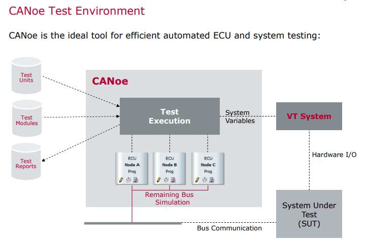
What is CANoe ?
CANoe is the comprehensive software tool for development, test and analysis of individual ECUs and entire ECU networks. It supports network designers, development and test engineers throughout the entire development process – from planning to system-level test.
Create and test individual ECUs or whole ECU networks. Perform various types of analyses and view the results using the Trace Window, Graphics Window, Statistics Window, Data Window, and State Tracker. Carry out the testing tasks in the manual or automated modes and identify error situations in the development process to fix them on time.
Canoe is very well known for its network simulation capabilities. The Canoe tool not only has the capability to simulate multiple nodes in network, it can also simulate multiple network of various bus types such as CAN,LIN,MOST .Canoe can be used to model all the network data and functions in these bus systems. When network data and functions need to be evaluated and validated at the design implementation or Production stage, CANoe can become a test tool as well as network simulation tool to test these network functions.
This is made Possible in CANoe with the Test Feature set it provides the user ability to implement and execute a sequential set of test instruction written in XML,CAPL or Both
Advantages
- Only one tool for all development and testing tasks
- Easy automated testing
- Extensive possibilities for simulating and testing ECU diagnostics
- Detect and correct error situations early in the development process
- User-friendly graphic and text-based evaluation of results
Manual Testing v/s Automation Testing: A Snapshot
| Manual Testing | Automation Testing |
| May take one week to 15 days to test a software module of an ECU (Electronic Control Unit). | Can be completed in half an hour or 1 hour |
| Testing multiple signals simultaneously is not possible | Multiple signals can be tested simultaneously using routines (part of code that performs some specific task) |
| Test reports are created manually using excel sheets. | Test reports are created automatically |
| Test-cases are written manually. | Test cases are written using script and can be re-used in other projects as well |
| Each test case must be run separately, thereby, increasing the time for testing | Multiple test cases can run simultaneously on different systems |
| Batch testing (keeping the test cases in queue for execution) is not possible. | Batch testing is possible without any manual interference |
| Performance testing cannot be done accurately | Stress testing, spike testing, load testing can be easily inserted into the test-case script |
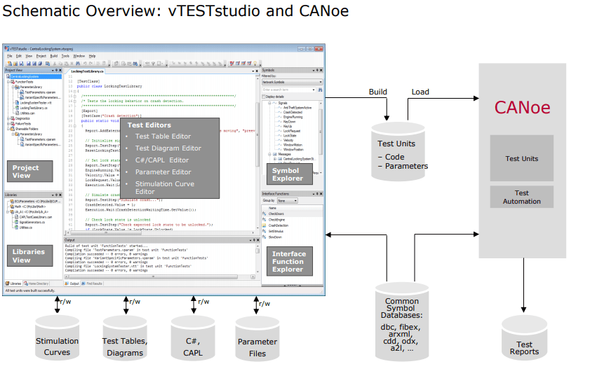
What is vTesT studio?
vTESTstudio is a powerful development environment for creating automated ECU tests. In order to increase the efficiency in terms of test design and to simplify the reusability it provides either
- programming-based,
- table-based and
- graphical test notations and test development methods.
What are the Value-Adds of Using vTest Studio for Automation of Testing:
- vTest Studio can cater to a broad range of ECU applications, as this tool is equipped with several test-case editors
- The test sequences can be given parameters with scalar values, test vectors written in multiple test design languages like CAPL, C# etc.
- Test projects can be created and maintained in a simple manner using the user-friendly GUI
- vTest Studio offers universal traceability of the test specifications defined externally
- This automation testing tool can also provide high test coverage, without the need for writing any complex test case scripts
- vTest Studio supports Open Interface, this facilitates easy integration with other automation tools = like CANoe.
How to Set-up Automated Testing Environment Using vTest Studio
Implementation of automation in testing, for an automotive electronic control unit (ECU), requires a set of tools (both hardware and software).
Essentially, while testing an ECU, we simulate it inside a test bench that mimics the actual vehicle environment.
The target is to validate all the functionalities of the ECU and its behavior against the given requirements.
The set-up should be such that the simulated environment exactly mimics the actual vehicle environment.
in order to set up such a test bench, the following three important components are required:
- vTest Studio– For writing the test cases in CAPL editor
- CANoe Testing tool– For executing the test cases
- CAN Case VN 1600/10/30- Network interface for CAN, LIN, K-Line, IO , in order to understand and visualize communication between the target ECU and the simulated ECU
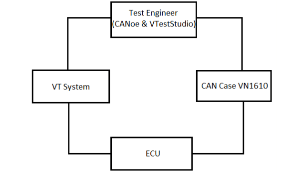
The three components mentioned above interact with each other to make the automation testing happen. Let’s now understand how they are setup to build a testing environment.
- ECU Pins are connected to the corresponding modules of the CANoe Hardware (CAN Case VN 1600), as per the project requirements. This piece of hardware is connected to the PC
- CANoe Tool is loaded with messages and CAN Databases, that are required for data to be transmitted between the ECUs along with the diagnostics services
- Using the CANoe tool GUI, the modules to be tested are loaded in the CANoe tool
- In the CANoe tool, these modules are configured as per the project requirements
- Now, vTest Studio is initiated and CANoe configuration (performed in step 4) is imported into it.
- The required environment for testing automation is now setup and vTest Studio is ready to design the relevant test cases.
This is the minimum setup required for the automation of the software testing of an automotive ECU (electronic control unit).
After the test cases are created, they are executed on the target control unit and reports are generated.
Understanding the Workflow of the Automated Testing of an Electronic Control Unit (ECU):
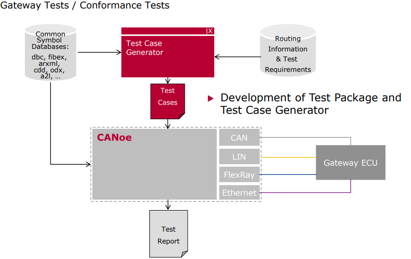
Step 1: Creation of Test Cases
- Scripting for test case creation is done in CAPL. It is a programming language very similar to ‘C’. CAPL was created by Vector to test Electronic Control Units using CANoe tool.
- Let’s say you are required to test three modules of an ECU (electronic control unit);viz; – Functionalities, Specifications and Error Handling. The test cases for these three modules will be designed in CAPL editor. All the test cases can be compiled as a single ‘build’ or multiple ones, depending on the modules to be tested.
Step 2: Execution of the Test Cases in CANoe tool
- Now, the build with all the test cases will be run on the target ECU using the CANoe tool. CANoe acts a separate ECU that interacts with the target ECU and runs the test cases.
- The response from the target ECU is displayed on the CANoe tool and test reports are generated.
The point to be noted here is, that vTest Studio is used only for creating the test cases. These test cases are run on a separate tool called CANoe.
So, these two tools (vTest Studio and CANoe) complement each other in carrying out automation testing of an electronic control unit.

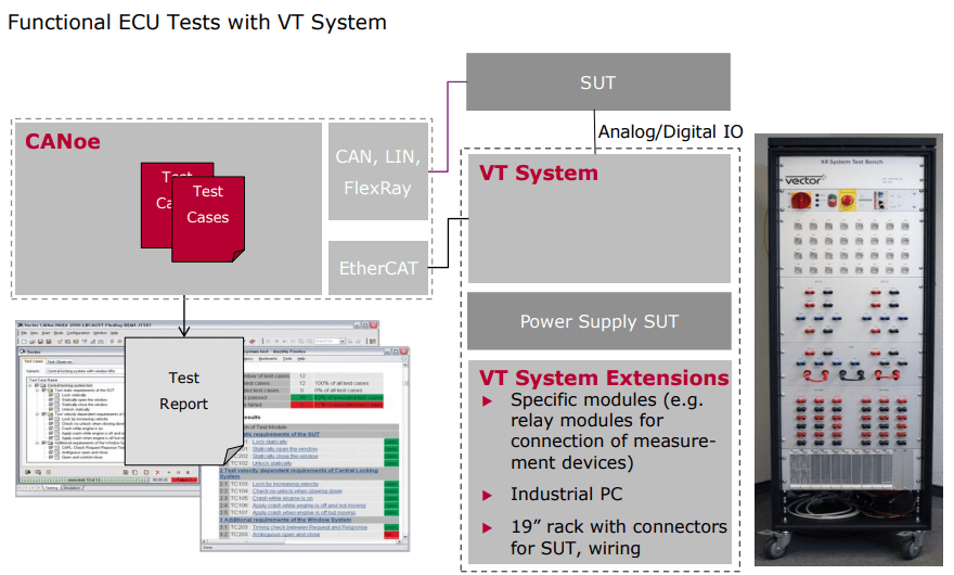
VT System Concept
The simulation of the loads and sensors are done using a Vector tool called VT System. It is important for the ECU to be in an environment that closely resembles that of the real vehicle. VT System fulfills these needs. The VT System is a modular I/O system that drives ECU inputs and outputs for functionality related testing with CANoe. It is able to create faults which should be detected by the ECU and display an error code. This is a way of partly testing an ECU .
The ECU’s I/O lines and any necessary sensors and actuators are connected to the VT System modules. The PC with CANoe is connected to the real-time Ether CAT via the computer’s Ethernet port .
The VT System is connected to ECU’s particular pins instead of the real loads such as LED channels in the headlamp. The loads and sensors are simulated by the VT System modules or panels. However these modules can also be connected to the original actuators and sensors. All equipments required for testing the connected ECU inputs or outputs are integrated into the VT System modules
The functions of VT System are
(1) It can be used to simulate loads or sensors
(2) It has relays for switching different signal paths (eg. internal or external load)
(3) It can be used to create faults such as short circuits between the two signal lines and signal to ground or battery voltage
(4) It also acts as a measuring unit with signal conditioning
(5) It is possible to connect additional measurement and test devices via two additional bus bars
(6) It displays status clearly on the front panel
The ECU’s output signals are measured and processed, and are passed to the test cases in VTestStudio in processed form so that they can be printed in the test report generated after the test cases are executed
ECU environment in the vehicle
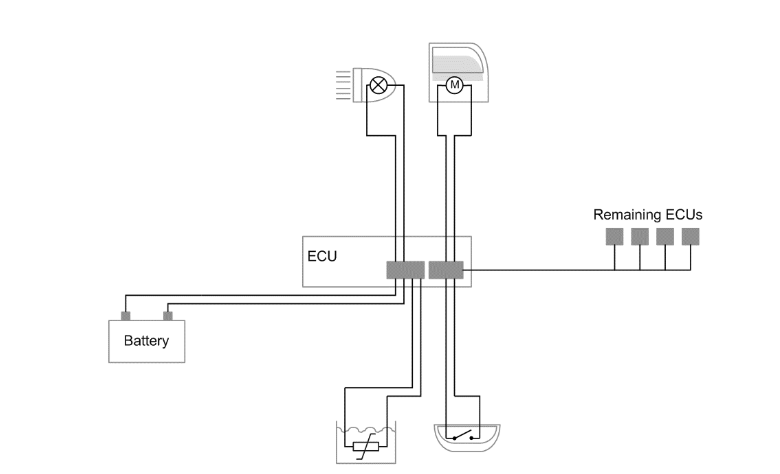
In the vehicle, an ECU communicates with other ECUs via bus interface; it is supplied with power from the battery and is connected to sensors and actuators via I/O lines.
Testing with original loads and sensors

The VT System is placed between the ECU’s I/O lines and the original sensors and acuators. CANoe executes the automated tests and simulates the rest of the network nodes.
Testing with simulated actuators and sensors

The VT System can also simulate the sensors and actuators. This lets you reconstruct any desired test situations and error cases.
Testing the functionality of ECU includes simulating it via software and hardware interfaces and evaluating its responses. It is important for the ECU to be in a surrounding that closely resembles that of the real vehicle, and most important is that the ECU should not be able to detect any difference between the actual environment in the vehicle and the simulated environment of the test bench. The use of tool CANoe for simulation of other ECUs in the car is well-suited for tests on all development phases, due to its high scalability and flexibility. Manual testing is performed by an engineer using the software tool in the computer, carefully executing the test steps constructed based on the requirements. Manual testing is time consuming and may not be very accurate. Test Engineer may feel it as a very tedious work as he has to test the same requirements in all the development phases of an ECU. So, automating these testing processes can help a lot for the Test Engineer. Automation Testing is using an automation tool to execute the test case suite. The automation software can also enter test data for the parameters in the services of an ECU, compare expected and actual results and generate detailed and validated test reports. Test Automation demands considerable investments of resources and money. Successive development phases will require execution of same test suite repeatedly. This is reusability of the test cases. Using a test automation tool called VTestStudio it is possible to document this test suite and use it as required. Any human intervention is not required once the test suite has been automated. The VT System is modular hardware for accessing ECU hardware inputs or outputs for testing purposes. The VT System can be easily integrated with CANoe and the test cases are scripted in VTestStudio. The actuator and sensor connections of the ECU to be tested are linked directly to the VT System modules. And ECU is also connected to CANoe through CAN case VN1610 for Understanding and visualizing CAN communication [5] between real ECU and simulated ECUs
Network Interfaces :
interface to inter connect your PC With CAN,CAN(FD),LIN, Ethernet bus system.
Software tools used to develop, simulate, test and maintain distributed systems require powerful and flexible network interfaces. Vector offers you interfaces for CAN (FD), LIN, J1708, Automotive Ethernet, FlexRay, 802.11p and MOST as well as driver software and programming interfaces for use with Vector software tools and in customer-specific solutions.
System Design Of Testing Environment :
All the pins of the ECU are connected to the particular modules of the VT System as per the requirements. VT System is connected to the computer through Ether CAT cable. CANoe will contain the database which has the messages to be transmitted between several ECUs, .cdd file containing the diagnostic services of the ECU and the other simulated ECUs attached to the periphery bus. CANoe with other simulated ECUs in the car is opened and then VT system configuration panel is opened in CANoe. All the modules connected in the VT System are added to CANoe. All the modules are configured as per requirements. For e.g. VT7001A module is configured with the supply mode as “sup1” as it is connected with the external power supply. CAN pins from the ECU are connected with the CAN case VN1610 and then the CAN case is connected to the computer using its USB cable. After this minimum setup, VTestStudio software is opened with the CANoe configuration imported to it. After importing the VTestStudio will contain the Messages present in the database, diagnostic services present in the .cdd file and the parameters of the VT System modules. Now the VTestStudio can be used to write test cases with having access to messages, diagnostic services and the VT System module parameters.
CAN Database
The CAN database defines the network nodes containing the CAN messages transmitted and received by them and the signals within each message. The names in this database can be imported in the VTestStudio for application in test cases and can also be used throughout the CANoe configuration. For example, displaying signal values in CANoe’s graphical output windows, or creating test cases in the VTestStudio.