What is a LIN Bus?
The Local Interconnect Network, or LIN Bus, plays a crucial role in facilitating communication between components within vehicles. Designed as a supplement to the more complex CAN Bus system, LIN offers a more economical means for connecting various parts of a car’s network.
While the LIN protocol is notably more cost-effective than its CAN counterpart, it does so by modestly scaling back in terms of performance and reliability. This balance of cost and functionality makes LIN an intelligent choice for less critical communication tasks.

What is a LIN protocol?
The LIN protocol is a structured system of wired communication specifically designed for electronic devices within vehicles. It operates on a master-slave architecture, where a single master device controls the communication flow to one or several slave devices.
Communication within the LIN network is organized into frames, each containing a header and a response. The master initiates the dialogue by sending out the header, while the response is provided by a designated slave or, in some cases, the master itself.
Additionally, the LIN protocol is designed with two distinct operational states: an active mode for regular communication and a sleep mode for energy conservation when the network is not in use.
The LIN specification has been repeatedly revised, and three types, LIN Revision 1.3, 2.0, and 2.1, are mainly used for automotive ECUs, but the last revision by the LIN Consortium was LIN Revision.2.2A. It has now been transferred to ISO, and the LIN specification was published as ISO17987 in August 2016. LIN is positioned as a sub-bus of CAN, making it possible to construct a network at a lower cost than CAN.
Key facts about LIN Bus
Here are key facts about the LIN Bus protocol, highlighting its functionality and design within vehicle communication systems:
- Cost-efficient solution.
- Single wire, capable of 1-20 kbit/s, up to 40m (+ground).
- Standard 12V operating voltage.
- Commonly used for vehicle subsystems like wipers and windows.
- Configurations include 1 master and up to 16 nodes.
- Modern vehicles often feature over 10 nodes.
- Supports various data lengths: 2, 4, and 8 bytes.
- Ensures timely data transfer with scheduled transmission.
- Features sleep mode and wake-up capabilities.
- Adheres to ISO 9141 – K-line for the physical layer.
- Includes error detection and configuration mechanisms.
LIN network construction example
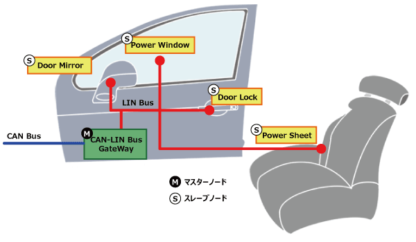
Today, LIN bus is a de facto standard in practically all modern vehicles – with examples of automotive use cases below:
- Steering wheel: Cruise control, wiper, climate control, radio
- Comfort: Sensors for temperature, sun roof, light, humidity
- Powertrain: Sensors for position, speed, pressure
- Engine: Small motors, cooling fan motors
- Air condition: Motors, control panel (AC is often complex)
- Door: Side mirrors, windows, seat control, locks
- Seats: Position motors, pressure sensors
- Other: Window wipers, rain sensors, headlights, airflow
Further, LIN bus is also being used in other industries:
- Home appliances: Washing machines, refrigerators, stoves
- Automation: Manufacturing equipment, metal working
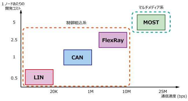
Positioning with other protocols
LIN bus history
Below we briefly recap the history of the LIN protocol:
- 1999: LIN 1.0 released by the LIN Consortium (BMW, VW, Audi, Volvo, Mercedes-Benz, Volcano Automotive & Motorola)
- 2000: The LIN protocol was updated (LIN 1.1, LIN 1.2)
- 2002: LIN 1.3 released, mainly changing the physical layer
- 2003: LIN 2.0 released, adding major changes (widely used)
- 2006: LIN 2.1 specification released
- 2010: LIN 2.2A released, now widely implemented versions
- 2010-12: SAE standardized LIN as SAE J2602, based on LIN 2.0
- 2016: CAN in Automation standardized LIN (ISO 17987:2016)
LIN FRAME FORMAT
The LIN frame format is straightforward, composed of two main components: a header and a response. In a typical exchange, the LIN master dispatches a header onto the bus, prompting a response from a designated slave node.
This response can carry a payload of up to 8 data bytes. The streamlined structure of the LIN frame is designed for efficient communication within the network. Below, you’ll find a detailed illustration of the LIN frame format, showcasing the precise way that messages are constructed and exchanged within the system.

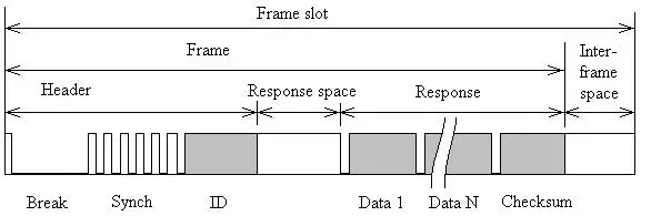
Break: The Sync Break Field (SBF) aka Break is minimum 13 + 1 bits long (and in practice most often 18 + 2 bits). The Break field acts as a “start of frame” notice to all LIN nodes on the bus.
13 dominant bits long including start bit. Synch break ends with a “break delimiter” which should be at least one recessive bit.
Sync: The 8 bit Sync field has a predefined value of 0x55 (in binary, 01010101). This structure allows the LIN nodes to determine the time between rising/falling edges and thus the baud rate used by the master node. This lets each of them stay in sync.
Identifier: The Identifier is 6 bits, followed by 2 parity bits. The ID acts as an identifier for each LIN message sent and which nodes react to the header. Slaves determine the validity of the ID field (based on the parity bits) and act via below:
- Ignore the subsequent data transmission
- Listen to the data transmitted from another node
- Publish data in response to the header
The Identifier determines the content of the message and also the priority; lower numerical values mean higher priority. Nodes on the network use this field to decide whether to ignore the message, to listen in, or to prepare a response for the frame’s data field that follows.
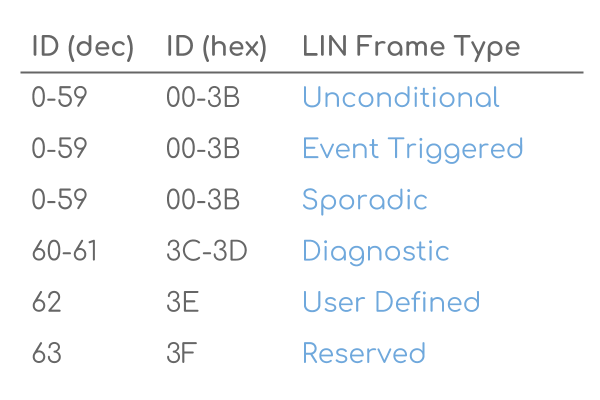
Typically, one slave is polled for information at a time – meaning zero collision risk (and hence no need for arbitration).Note that the 6 bits allow for 64 IDs, of which ID 60-61 are used for diagnostics (more below) and 62-63 are reserved.
The parity bits are calculated as followed: parity P0 is the result of logic “XOR” between ID0, ID1, ID2 and ID4. Parity P1 is the inverted result of logic “XOR” between ID1, ID3, ID4 and ID5.
Data: When a LIN slave is polled by the master, it can respond by transmitting 2, 4 or 8 bytes of data. The data length can be customized, but it is typically linked to the ID range (ID 0-31: 2 bytes, 32-47: 4 bytes, 48-63: 8 bytes). The data bytes contain the actual information being communicated in the form of LIN signals. The LIN signals are packed within the data bytes and may be e.g. just 1 bit long or multiple bytes.
Checksum: As in CAN, a checksum field ensures the validity of the LIN frame. The classic 8 bit checksum is based on summing the data bytes only (LIN 1.3), while the enhanced checksum algorithm also includes the identifier field (LIN 2.0)
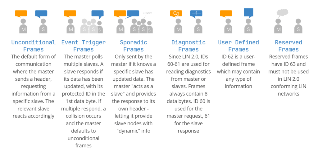
Six LIN frame types
Multiple types of LIN frames exist, though in practice the vast majority of communication is done via “unconditional frames”.
Note also that each of the below follow the same basic LIN frame structure – and only differ by timing or content of the data bytes.
LIN Bus vs. CAN Bus
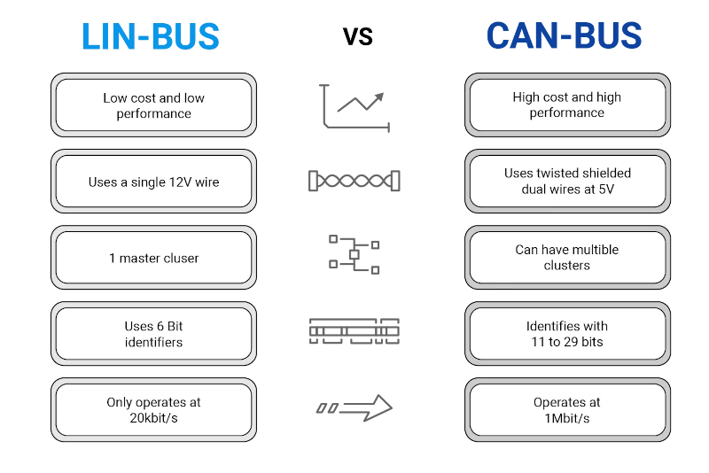
- LIN is lower cost (less harness, no license fee, cheap nodes)
- CAN uses twisted shielded dual wires 5V vs LIN single wire 12V
- A LIN master typically serves as gateway to the CAN bus
- LIN is deterministic, not event driven (i.e. no bus arbitration)
- LIN clusters have a single master – CAN can have multiple
- CAN uses 11 or 29 bit identifiers vs 6 bit identifiers in LIN
- CAN offers up to 1 Mbit/s vs. LIN at max 20 kbit/s
The LIN Node Configuration File (NCF) and LIN Description File (LDF)
The LIN network is described by a LDF (LIN Description File) which contains information about frames and signals. This file is used for creation of software in both master and slave.
The master node controls and make sure that the data frames are sent with the right interval and periodicity and that every frame gets enough time space on the bus. This scheduling is based on a LCF (LIN Configuration File) which is downloaded to the master node software.
All data is sent in a frame which contains a header, a response and some response space so the slave will have time to answer. Every frame is sent in a frame slot determined by the LCF.
LIN Bus: Streamlining Communication
- Known for its straightforwardness and affordability, LIN Bus provides a streamlined option for vehicle communication.
- With a clear master-slave relationship, it ensures organized dialogue between one master and several slaves.
- LIN Bus shines in managing simple tasks such as adjusting mirrors, seats, and operating wipers.
- To save power the slave nodes will be put in a sleep mode after 4 seconds of bus inactivity or if the master has sent a sleep command. Wakeup from sleep mode is done by a dominant level on the bus which all nodes can create.
CAN Bus: The Nerve Center of Auto Communication
- CAN Bus stands out for its capacity to handle essential, data-heavy systems like the engine and safety mechanisms.
- Positioned at the heart of the vehicle’s network, CAN Bus orchestrates complex communication.
- It teams up with LIN Bus, allowing LIN to take on the simpler tasks, thereby enhancing the network’s efficiency.
Refrences
